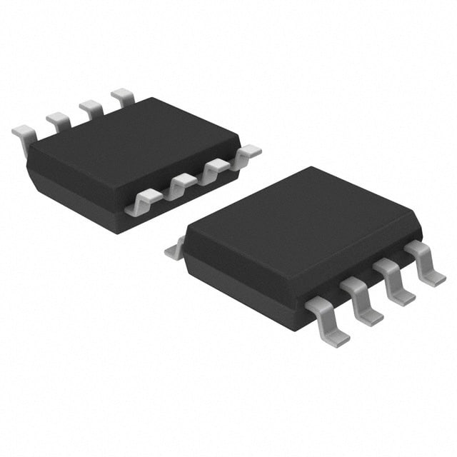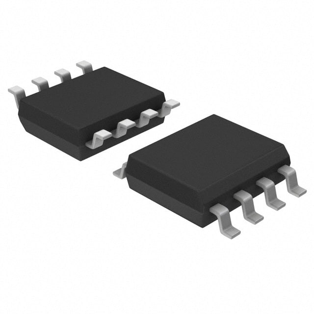
The PCA82C251T/YM CAN transceiver, developed by TI, is integral to modern communication systems. It functions as a critical interface for telecommunications and industrial automation, ensuring robust data exchange. Mastering its integration is essential for engineers and developers aiming to enhance system reliability and performance. A step-by-step approach simplifies the integration process, making it accessible even to those new to this technology. By understanding each phase, individuals can effectively implement the PCA82C251T/YM, leading to successful applications across various industries.
Step 1: Understanding the PCA82C251T/YM
Key Features of PCA82C251T/YM
The PCA82C251T/YM transceiver, developed by NXP, stands out as a reliable interface for telecommunications and industrial automation. This component supports high-speed communication, operating at data rates up to 1 Mbps. It functions efficiently within a supply voltage range of 4.5V to 5.5V, making it suitable for various applications. The transceiver’s robust performance ensures reliable operation even in harsh environments, with an operating temperature range from -40°C to 125°C.
Overview of the Transceiver’s Specifications
-
High-Speed Communication: Supports data rates up to 1 Mbps.
-
Supply Voltage Range: Operates between 4.5V and 5.5V.
-
Temperature Range: Functions reliably from -40°C to 125°C.
-
Compatibility: Adheres to the ISO 11898-24 V standard.
Applications in Various Industries
The PCA82C251T/YM finds applications across multiple sectors:
-
Industrial Automation: Enhances communication in programmable logic controllers (PLCs) and robotics.
-
Telecommunications: Supports network equipment and monitoring systems.
-
Automotive Systems: Facilitates communication in advanced driver assistance systems (ADAS) and engine control units (ECUs).
Benefits of Using PCA82C251T/YM
The PCA82C251T/YM offers several advantages over other transceivers, making it a preferred choice for engineers and developers.
Advantages Over Other Transceivers
-
Robust Performance: High noise immunity ensures reliable operation in demanding environments.
-
Low Power Consumption: Ideal for battery-operated devices and energy-efficient applications.
-
Versatility: Suitable for a wide range of applications, from automotive to industrial automation.
Real-World Examples of Successful Integration
In real-world scenarios, the PCA82C251T/YM has proven its effectiveness. For instance, in industrial automation, it enhances communication between various automation components, improving system reliability and performance. In telecommunications, it supports efficient data exchange, contributing to improved network reliability.
Step 2: Technical Aspects of Integration
Component Placement
Proper component placement on the PCB plays a crucial role in the successful integration of the PCA82C251T/YM. Engineers must follow specific guidelines to ensure optimal performance.
Guidelines for Optimal Placement on PCB
-
Proximity to Microcontroller: Place the PCA82C251T/YM close to the microcontroller. This minimizes signal path lengths, reducing potential interference.
-
Orientation: Align the transceiver with other components to facilitate efficient routing of traces.
-
Thermal Management: Ensure adequate spacing from heat-generating components. This prevents overheating and maintains the transceiver’s reliability.
Common Pitfalls to Avoid
-
Inadequate Grounding: Poor grounding can lead to signal integrity issues. Ensure a solid ground plane beneath the PCA82C251T/YM.
-
Improper Trace Widths: Use appropriate trace widths to handle the current requirements. This prevents voltage drops and maintains signal quality.
-
Ignoring Manufacturer’s Recommendations: Always adhere to TI’s guidelines for the PCA82C251T/YM. This ensures compatibility and optimal performance.
Power Supply Decoupling
Power supply decoupling is vital for maintaining the stability of the PCA82C251T/YM. It reduces noise and enhances the transceiver’s performance.
Importance of Decoupling Capacitors
Decoupling capacitors filter out voltage spikes and noise from the power supply. They provide a stable voltage to the PCA82C251T/YM, ensuring reliable operation in telecommunications and industrial automation applications.
Recommended Configurations
-
Capacitor Placement: Position decoupling capacitors as close as possible to the power pins of the PCA82C251T/YM.
-
Capacitor Values: Use a combination of capacitors, such as a 100nF ceramic capacitor in parallel with a 10µF tantalum capacitor. This configuration effectively filters high-frequency noise and stabilizes the power supply.
Adherence to ISO 11898-24 V Standard
Compliance with the ISO 11898-24 V standard is essential for the PCA82C251T/YM. It ensures reliable communication in industrial automation systems.
Ensuring Compliance with the Standard
-
Signal Integrity: Maintain signal integrity by following the standard’s guidelines for trace routing and termination.
-
Voltage Levels: Ensure that the voltage levels meet the standard’s requirements. This guarantees compatibility with other devices in the network.
Benefits of Standard Adherence
-
Interoperability: Adhering to the ISO 11898-24 V standard ensures that the PCA82C251T/YM interfaces seamlessly with other compliant devices.
-
Reliability: Compliance enhances the reliability of communication systems in telecommunications and industrial automation, reducing the risk of data loss or corruption.
Step 3: Testing and Troubleshooting
Testing Procedures
Testing the PCA82C251T/YM integration is crucial for ensuring optimal performance in telecommunications and industrial automation systems. Engineers must follow a structured approach to verify the functionality of this TI interface.
Initial Testing Setup
-
Prepare the Test Environment: Set up a controlled environment to test the PCA82C251T/YM. Use a stable power supply and ensure all connections are secure.
-
Connect to a Microcontroller: Interface the transceiver with a compatible microcontroller. This setup allows for the simulation of real-world communication scenarios.
-
Monitor Signal Transmission: Use an oscilloscope to observe signal integrity. Check for any anomalies in the waveform that may indicate issues with the transceiver.
Performance Evaluation Techniques
-
Data Rate Testing: Verify that the PCA82C251T/YM supports data rates up to 1 Mbps. This ensures the transceiver meets the requirements for high-speed communication.
-
Noise Immunity Assessment: Introduce controlled noise into the system. Evaluate the transceiver’s ability to maintain reliable communication under these conditions.
-
Temperature Stress Testing: Test the transceiver across its operating temperature range, from -40°C to 125°C. Confirm that it performs reliably in both extreme cold and heat.
Troubleshooting Common Issues
Even with careful integration, issues may arise. Identifying and resolving these problems ensures the PCA82C251T/YM functions as intended in telecommunications and industrial automation applications.
Identifying and Resolving Signal Integrity Problems
-
Check Ground Connections: Poor grounding often leads to signal integrity issues. Ensure a solid ground plane exists beneath the PCA82C251T/YM.
-
Inspect Trace Routing: Examine the PCB layout for improper trace routing. Adjust traces to minimize interference and maintain signal quality.
-
Evaluate Component Placement: Reassess the placement of components on the PCB. Ensure the transceiver is positioned optimally to reduce potential interference.
Tips for Optimizing Transceiver Performance
-
Use Quality Components: Select high-quality capacitors and resistors. These components contribute to the overall stability and performance of the PCA82C251T/YM.
-
Regular Maintenance: Periodically inspect the system for wear and tear. Replace any damaged components to maintain optimal performance.
-
Update Firmware: Keep the microcontroller firmware up to date. This ensures compatibility with the PCA82C251T/YM and enhances system reliability.
The integration process of the PCA82C251T/YM involves understanding its features, technical aspects, and testing procedures. By following these steps, engineers can ensure successful implementation in various applications. Applying these guidelines in real-world projects enhances system reliability and performance. Mastering the PCA82C251T/YM integration offers significant benefits, including improved communication efficiency and robust operation in demanding environments. This knowledge empowers developers to create innovative solutions across industries, contributing to advancements in telecommunications and industrial automation.
See Also
Best Methods for Incorporating MC9S12XET512VAG
Revolutionizing Industrial Automation with ATIC83E2
Essential Programming Tips for MC9S12XD256 Microcontrollers
Effortless Integration of Sensors with SN74LVC4245APW
Diving into MC9S12DJ256MFUE Specs for Automotive Uses

