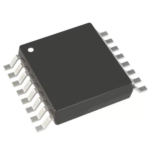
The AD5235BRUZ25 serves as a dual-channel digital potentiometer with 1024 adjustable positions, offering precise control over resistance. Its design ensures accurate sensor calibration and filter tuning in various applications. The device features non-volatile memory, which retains settings even after power loss. Its SPI-compatible interface simplifies integration with microcontrollers, enabling seamless adjustments. Engineers and technicians can rely on this tool for stable and repeatable resistance modifications, making it an essential component in systems requiring fine-tuned performance.
Key Takeaways
-
The AD5235BRUZ25 features a dual-channel design with 1024 adjustable positions, allowing for precise resistance control essential for sensor calibration and filter tuning.
-
Its non-volatile memory retains settings even after power loss, ensuring that configurations remain intact and reducing the need for frequent reconfiguration.
-
The SPI-compatible interface simplifies integration with microcontrollers, enabling efficient programming and seamless adjustments in various applications.
-
Engineers can achieve accurate sensor calibration by fine-tuning resistance values, aligning sensor outputs with desired characteristics for reliable measurements.
-
For filter tuning, adjusting resistance with the AD5235BRUZ25 allows precise control over parameters like cut-off frequency, optimising signal processing performance.
-
Proper setup and connection are crucial; ensure stable power delivery and verify all connections to prevent operational issues.
-
Regularly verify resistance values during operation to maintain accuracy and reliability, utilising the device’s read-back functionality for confirmation.
Overview of the AD5235BRUZ25
The AD5235BRUZ25 stands out as a versatile digital potentiometer, offering precision and adaptability for various applications. Its design incorporates advanced features that cater to the needs of engineers and technicians seeking reliable resistance adjustments. This section explores the key features and specifications of the device, along with its practical applications.
Key Features and Specifications
Dual-channel design and 25 kΩ resistance
The AD5235BRUZ25 features a dual-channel configuration, enabling simultaneous control of two independent resistance paths. Each channel provides a nominal resistance of 25 kΩ, making it suitable for applications requiring balanced or separate resistance adjustments. This dual-channel design enhances flexibility in circuit designs.
1024-position resolution for fine adjustments
With 1024 discrete wiper positions, the AD5235BRUZ25 ensures precise resistance tuning. This high resolution allows users to make fine adjustments, which is essential for achieving accurate sensor calibration and filter tuning. The ability to increment or decrement resistance in small steps provides exceptional control over the desired output.
Non-volatile memory for retaining settings
The device includes non-volatile memory, which retains the wiper settings even after power loss. This feature ensures that the configured resistance values remain intact, eliminating the need for reconfiguration during power cycles. It also supports storing user-defined information, such as lookup tables or data for other components, enhancing its utility.
SPI-compatible interface for easy integration
The AD5235BRUZ25 operates through an SPI-compatible serial interface, simplifying its integration with microcontrollers and digital systems. This interface enables seamless communication, allowing users to program and adjust resistance values efficiently. The SPI compatibility ensures compatibility with a wide range of embedded systems.
Applications of the AD5235BRUZ25
Sensor calibration and filter tuning
The AD5235BRUZ25 excels in sensor calibration by enabling precise resistance adjustments. It allows users to fine-tune sensor outputs to match desired response characteristics. In filter tuning, the device adjusts resistance to modify parameters like cut-off frequency, ensuring optimal signal processing.
Programmable gain amplifiers and offset adjustment
This digital potentiometer plays a crucial role in programmable gain amplifiers (PGAs). It allows users to set amplifier gains with precision, enhancing the performance of analogue signal processing systems. Additionally, it facilitates offset and zero adjustments in measurement instruments, ensuring accurate readings.
Volume control and power supply voltage adjustment
The AD5235BRUZ25 serves as an excellent tool for volume control in audio equipment. Its fine resolution ensures smooth and repeatable volume adjustments. Furthermore, it enables precise power supply voltage adjustments, making it valuable in programmable power supplies and other voltage-sensitive applications.
“The AD5235 allows multiple modes of operation, including read/write access, resistance changes in ±6 dB scales, and wiper setting read-back.”
This versatility makes the AD5235BRUZ25 a reliable choice for applications requiring stable and dynamic resistance control.
Setting Up the AD5235BRUZ25
Proper setup of the AD5235BRUZ25 ensures optimal performance in sensor calibration and filter tuning tasks. This section provides a detailed guide to connecting the device and configuring it for first-time use.
Step-by-Step Connection Guide
Connecting the AD5235BRUZ25 to a microcontroller
To integrate the AD5235BRUZ25 with a microcontroller, users must establish a reliable connection between the two devices. Begin by identifying the SPI pins on the microcontroller, which typically include MOSI (Master Out Slave In), MISO (Master In Slave Out), SCLK (Serial Clock), and CS (Chip Select). Connect these pins to the corresponding terminals on the AD5235BRUZ25. Ensure that the MOSI pin on the microcontroller links to the SDI (Serial Data Input) pin on the potentiometer. Similarly, connect the SCLK pin to the SCL (Serial Clock) pin and the CS pin to the CS terminal.
For the power supply, attach the VDD pin of the AD5235BRUZ25 to the positive voltage source and the GND pin to the ground. If using dual supplies, connect VSS to the negative voltage source. Verify all connections to prevent errors during operation.
Understanding the pin configurations
The AD5235BRUZ25 features a straightforward pin layout. The device includes two independent channels, each with three terminals: A, B, and W. Terminals A and B represent the fixed ends of the resistor, while terminal W serves as the wiper. Adjusting the wiper position alters the resistance between these terminals.
The SPI interface pins—SDI, SDO (Serial Data Output), SCL, and CS—facilitate communication with the microcontroller. The VDD and GND pins provide power, while the VSS pin supports dual-supply configurations. Familiarity with these pin functions simplifies the integration process.
Power Requirements and Initial Configuration
Voltage supply options (single and dual supply)
The AD5235BRUZ25 operates with either a single or dual power supply. For single-supply operation, provide a voltage range of 2.7 V to 5 V to the VDD pin. Dual-supply operation requires ±2.25 V to ±2.75 V, with VDD connected to the positive source and VSS to the negative source. Select the appropriate supply based on the application requirements.
Stable power delivery is crucial for consistent performance. Use decoupling capacitors near the power pins to minimise noise and voltage fluctuations. This practice enhances the reliability of the device in sensitive applications.
Configuring the device for first use
Before using the AD5235BRUZ25, initialise the device through the SPI interface. Send a command to set the wiper positions to their default values. This step ensures that the resistance starts at a known state. Refer to the datasheet for the specific command format and timing requirements.
Test the communication between the microcontroller and the AD5235BRUZ25 by reading back the wiper settings. Successful read-back confirms proper configuration and readiness for operation. Once verified, proceed to adjust the resistance values as needed for the intended application.
Using the AD5235BRUZ25 for Sensor Calibration
Understanding Sensor Calibration
Definition and importance of sensor calibration
Sensor calibration refers to the process of adjusting a sensor’s output to ensure it accurately reflects the measured parameter. Sensors often exhibit deviations due to manufacturing tolerances, environmental factors, or ageing. Calibration corrects these deviations, ensuring reliable and precise measurements.
Accurate calibration is critical in applications such as industrial automation, medical devices, and environmental monitoring. For instance, a temperature sensor must provide precise readings to maintain optimal conditions in sensitive environments. Without proper calibration, sensors may produce inaccurate data, leading to errors in decision-making or system performance.
Role of resistance adjustment in calibration
Resistance adjustment plays a pivotal role in sensor calibration. Many sensors rely on resistive elements to determine their output. By fine-tuning the resistance, engineers can align the sensor’s response with the desired measurement range. The AD5235BRUZ25, with its 1024-position resolution, offers exceptional control over resistance values, making it an ideal tool for this purpose.
For example, in a voltage divider configuration, the AD5235BRUZ25 allows users to adjust the resistance until the sensor’s output matches the expected value. This capability ensures that the sensor operates within its optimal range, enhancing accuracy and reliability.
Practical Steps for Calibration
Adjusting resistance values to fine-tune sensor outputs
To calibrate a sensor using the AD5235BRUZ25, follow these steps:
-
Connect the sensor and the AD5235BRUZ25: Integrate the sensor into a circuit where the AD5235BRUZ25 controls the resistance. Ensure proper connections between the sensor, the potentiometer, and the microcontroller.
-
Establish communication: Use the SPI interface to communicate with the AD5235BRUZ25. Verify the connection by reading the initial wiper position.
-
Measure the sensor’s output: Record the sensor’s output under known conditions. Compare this output to the expected value to identify any discrepancies.
-
Adjust the resistance: Incrementally modify the resistance using the AD5235BRUZ25. Monitor the sensor’s output after each adjustment. Continue this process until the output aligns with the expected value.
-
Verify the calibration: Test the sensor under various conditions to ensure consistent accuracy. Store the final resistance settings in the AD5235BRUZ25’s non-volatile memory for future use.
This step-by-step approach ensures precise calibration, leveraging the AD5235BRUZ25’s high resolution and stability.
Example: Calibrating a temperature sensor for accuracy
Consider a temperature sensor used in a climate control system. The sensor’s output voltage corresponds to the ambient temperature, but slight inaccuracies affect the system’s performance. The AD5235BRUZ25 can address this issue.
-
Set up the circuit: Connect the temperature sensor and the AD5235BRUZ25 in a voltage divider configuration. Link the potentiometer to a microcontroller for SPI communication.
-
Measure the baseline output: Place the sensor in an environment with a known temperature. Record the sensor’s output voltage and compare it to the expected value.
-
Adjust the resistance: Use the AD5235BRUZ25 to fine-tune the resistance. Modify the wiper position until the sensor’s output matches the expected voltage for the given temperature.
-
Test across a range of temperatures: Repeat the process at different temperatures to ensure the calibration holds across the sensor’s operating range.
-
Store the settings: Save the final resistance values in the AD5235BRUZ25’s non-volatile memory. This step ensures the calibration remains intact even after power loss.
By following these steps, the AD5235BRUZ25 enables precise and repeatable calibration, improving the sensor’s accuracy and reliability.
Using the AD5235BRUZ25 for Filter Tuning
Filter tuning plays a critical role in signal processing, enabling engineers to optimise system performance by adjusting key parameters. The AD5235BRUZ25 offers precise resistance control, making it an ideal tool for fine-tuning filters in various applications. This section explores the concept of filter tuning and provides practical steps for achieving optimal results.
Understanding Filter Tuning
Definition and importance of filter tuning in signal processing
Filter tuning refers to the process of adjusting a filter’s parameters to achieve the desired signal characteristics. Filters are essential in signal processing, as they isolate or enhance specific frequency components. Proper tuning ensures that filters perform effectively, whether in audio systems, communication devices, or industrial equipment.
Accurate tuning is vital for maintaining signal integrity. For instance, in audio applications, poorly tuned filters can distort sound quality, while in communication systems, they may cause signal loss or interference. By fine-tuning filters, engineers can optimise performance and ensure reliable operation across various conditions.
How resistance impacts filter parameters like cut-off frequency
Resistance directly influences key filter parameters, such as the cut-off frequency. In RC (resistor-capacitor) circuits, the cut-off frequency depends on the resistance and capacitance values. Adjusting the resistance alters the time constant, which shifts the cut-off frequency and modifies the filter’s behaviour.
The AD5235BRUZ25, with its 1024-position resolution, allows precise resistance adjustments. This capability enables engineers to fine-tune filters with high accuracy. A study on RC time constant calibration highlights the importance of eliminating parasitic effects and minimising offsets during tuning. The AD5235BRUZ25 supports such precision, ensuring optimal filter performance.
Practical Steps for Filter Tuning
Adjusting resistance to modify filter behaviour
To tune a filter using the AD5235BRUZ25, follow these steps:
-
Set up the circuit: Connect the filter circuit to the AD5235BRUZ25, ensuring proper integration with a microcontroller for SPI communication. Verify all connections to avoid errors during operation.
-
Measure the filter’s response: Use a signal generator and an oscilloscope to analyse the filter’s frequency response. Identify the current cut-off frequency and compare it to the desired value.
-
Adjust the resistance: Incrementally modify the resistance using the AD5235BRUZ25. Monitor the changes in the filter’s response after each adjustment. Continue until the cut-off frequency aligns with the target value.
-
Test the filter’s performance: Evaluate the filter under different conditions to ensure consistent behaviour. Verify that the adjustments meet the application’s requirements.
-
Store the settings: Save the final resistance values in the AD5235BRUZ25‘s non-volatile memory. This step ensures that the tuning remains intact even after power loss.
This method provides a systematic approach to filter tuning, leveraging the AD5235BRUZ25‘s precision and stability.
Example: Tuning an audio filter for optimal sound quality
Consider an audio system requiring a low-pass filter to eliminate high-frequency noise. The AD5235BRUZ25 can help achieve the desired sound quality.
-
Connect the filter circuit: Integrate the low-pass filter with the AD5235BRUZ25. Link the potentiometer to a microcontroller for SPI-based control.
-
Analyse the initial response: Use an audio signal generator to input a range of frequencies. Measure the filter’s output to determine the current cut-off frequency.
-
Adjust the resistance: Modify the resistance using the AD5235BRUZ25 to shift the cut-off frequency. Focus on achieving a smooth transition between the passband and stopband.
-
Evaluate the sound quality: Test the filter with actual audio signals. Listen for improvements in clarity and noise reduction.
-
Finalise and save settings: Once satisfied with the tuning, store the resistance values in the AD5235BRUZ25‘s memory. This ensures consistent performance during future use.
By following these steps, engineers can optimise audio filters, enhancing sound quality and user experience.
Troubleshooting and Best Practices
Common Issues and Solutions
Incorrect connections or configurations
Improper connections or misconfigured settings often cause operational issues with the AD5235BRUZ25. Users may encounter communication errors or unexpected resistance values if the SPI pins are not correctly linked to the microcontroller. For instance, reversing the MOSI and MISO connections can disrupt data transmission. Similarly, neglecting to connect the CS (Chip Select) pin properly may prevent the device from responding to commands.
To resolve these issues, users should:
-
Double-check all wiring against the datasheet’s pin configuration.
-
Ensure that the SPI pins (MOSI, MISO, SCLK, and CS) are securely connected to their respective terminals.
-
Verify that the power supply pins (VDD, GND, and VSS for dual supply) are correctly attached and stable.
Testing the SPI communication by reading back the wiper position can confirm whether the connections are functioning as intended.
Power supply inconsistencies
Inconsistent or unstable power supplies can lead to erratic behaviour in the AD5235BRUZ25. Voltage fluctuations may cause the device to lose its settings or fail to operate within its specified parameters. For example, insufficient decoupling near the power pins can introduce noise, affecting the device’s performance.
To address power-related issues:
-
Use decoupling capacitors close to the VDD and GND pins to minimise noise and stabilise the voltage supply.
-
Ensure that the power source provides a consistent voltage within the recommended range (2.7 V to 5 V for single supply or ±2.25 V to ±2.75 V for dual supply).
-
Regularly monitor the power supply to detect and correct any irregularities.
Stable power delivery ensures reliable operation and prevents unnecessary interruptions.
Tips for Optimal Performance
Ensuring stable power supply and connections
Maintaining a stable power supply is crucial for achieving optimal performance with the AD5235BRUZ25. Voltage fluctuations or noisy power sources can compromise the device’s accuracy and reliability. Engineers should prioritise the following practices:
-
Place high-quality decoupling capacitors (e.g., 0.1 µF ceramic capacitors) near the power pins to filter out noise.
-
Use a regulated power supply to provide consistent voltage levels.
-
Inspect all connections periodically to ensure they remain secure and free from corrosion or damage.
Reliable connections between the AD5235BRUZ25 and the microcontroller also play a vital role. Loose or intermittent connections can disrupt communication and lead to errors. Verifying the integrity of the wiring during setup and routine maintenance helps prevent such issues.
Regularly verifying resistance values during operation
Regular verification of resistance values ensures that the AD5235BRUZ25 operates as expected. Over time, environmental factors or accidental changes in settings may alter the resistance, affecting the system’s performance. Routine checks help identify and correct such deviations promptly.
To verify resistance values:
-
Use the SPI interface to read the current wiper position.
-
Compare the read-back value with the expected resistance setting.
-
Adjust the wiper position if discrepancies arise.
Storing the final resistance settings in the device’s non-volatile memory provides an additional layer of security. This practice ensures that the configured values remain intact even after power loss, reducing the need for frequent recalibration.
“Consistency in power delivery and regular monitoring of resistance values are key to maintaining the AD5235BRUZ25’s precision and reliability.”
By following these best practices, users can maximise the performance and longevity of the AD5235BRUZ25 in their applications.
The AD5235BRUZ25 provides a reliable solution for sensor calibration and filter tuning. Its 1024-position resolution ensures precise resistance adjustments, while the non-volatile memory retains settings even after power loss. The SPI interface simplifies integration with digital systems, enabling efficient programming and control. By following the outlined steps, users can achieve consistent and accurate results in their projects. This versatile tool supports a wide range of applications, making it an essential component for engineers seeking precision and stability in their designs.
What is the AD5235BRUZ25 used for?
The AD5235BRUZ25 serves as a digital potentiometer designed for precise resistance adjustments. Engineers use it for tasks such as sensor calibration, filter tuning, programmable gain amplifiers, and volume control. Its versatility makes it suitable for applications in audio systems, industrial automation, and communication devices.
How does the AD5235BRUZ25 retain its settings after power loss?
The AD5235BRUZ25 features non-volatile memory, which stores the wiper settings even when the device loses power. This capability ensures that the configured resistance values remain intact, eliminating the need for reconfiguration during power cycles.
Can the AD5235BRUZ25 operate with both single and dual power supplies?
Yes, the AD5235BRUZ25 supports both single and dual power supply configurations. For single-supply operation, it requires a voltage range of 2.7 V to 5 V. For dual-supply operation, it operates within ±2.25 V to ±2.75 V. Users can select the appropriate configuration based on their application requirements.
How does the SPI interface simplify integration?
The SPI-compatible interface allows seamless communication between the AD5235BRUZ25 and microcontrollers. It enables users to program and adjust resistance values efficiently. The interface also supports read-back functionality, which helps verify the wiper position and ensures proper operation.
What makes the AD5235BRUZ25 suitable for sensor calibration?
The AD5235BRUZ25 offers 1024 discrete wiper positions, providing fine control over resistance adjustments. This high resolution allows engineers to align sensor outputs with desired response characteristics. Its stability and precision make it an ideal tool for achieving accurate and reliable sensor calibration.
How does resistance adjustment impact filter tuning?
Resistance directly influences key filter parameters, such as the cut-off frequency in RC circuits. Adjusting the resistance alters the time constant, which shifts the cut-off frequency and modifies the filter’s behaviour. The AD5235BRUZ25 enables precise resistance changes, allowing engineers to fine-tune filters for optimal performance.
What are the common issues encountered when using the AD5235BRUZ25?
Users may face issues such as incorrect connections, misconfigured settings, or unstable power supplies. Improper wiring of SPI pins or insufficient decoupling capacitors near the power pins can disrupt the device’s operation. Regular checks and adherence to best practices help prevent these problems.
How can users verify the resistance settings during operation?
Users can verify resistance settings by reading the current wiper position through the SPI interface. Comparing the read-back value with the expected resistance setting ensures accuracy. If discrepancies arise, users can adjust the wiper position to restore the desired resistance.
Is the AD5235BRUZ25 suitable for audio applications?
Yes, the AD5235BRUZ25 is highly suitable for audio applications. It provides precise volume control and enables fine-tuning of audio filters. Its high resolution ensures smooth adjustments, enhancing sound quality and user experience in audio systems.
What are the best practices for ensuring optimal performance?
To achieve optimal performance, users should maintain a stable power supply and secure connections. Using decoupling capacitors near the power pins minimises noise and voltage fluctuations. Regularly verifying resistance values and storing settings in non-volatile memory further enhances reliability and consistency.
See Also
Simple Guide For Integrating The SN74LVC4245APW Sensor
Utilising The ADXL357BEZ For Motion Sensing And Stability
Enhancing Process Control With The AD74413RBCPZ Chip
Understanding MC9S12DJ256MFUE Specs For Automotive Use
Key Features Of The FREESCALE MCF5251CVM140 In Automotive


