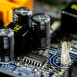
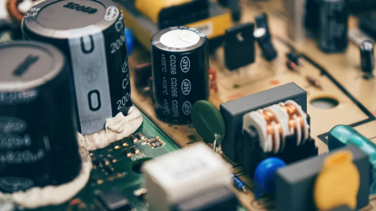
From your smartphone to your car, capacitors are everywhere! Multilayer ceramic capacitors (MLCCs) are present in nearly every electronic device imaginable. A capacitor is a component that stores electrical energy. It typically consists of two parallel conductive plates. Understanding capacitor characteristics is crucial for anyone working with electronics. Choosing the wrong capacitor can lead to circuit failure, poor performance, or even damage to a circuit that uses a capacitor. Mastering the Technical Specifications of Capacitors ensures proper function. This blog post aims to demystify capacitor characteristics and make the capacitor datasheet explained clearly. It empowers readers to confidently select the right capacitor for their projects.
Key Takeaways
-
Capacitors store electrical energy. They are important parts in almost all electronic devices.
-
Key features of a capacitor include its ability to store charge (capacitance), its maximum safe voltage (voltage rating), and its internal resistance (ESR). These features help you choose the right capacitor.
-
A capacitor’s datasheet is like a map. It shows all the important details about the capacitor. Learning to read it helps you pick the best one for your project.
-
Different types of capacitors exist, like ceramic and electrolytic. Each type works best for different jobs. Pick the right type for your circuit to make it work well.
-
Choosing the wrong capacitor can cause problems. Always match the capacitor’s features to your circuit’s needs to avoid issues.
Capacitor Fundamentals: What They Are & How They Work
Defining a Capacitor
A capacitor is a fundamental electronic component. It stores electrical energy. A capacitor typically consists of two main parts. These are conductive plates and a dielectric material. The conductive plates are usually made of metal. They serve as surfaces where electrical charges accumulate. The dielectric material is an insulating substance. It sits between the conductive plates. Its main job is to stop positive and negative charges from canceling each other out. This allows the capacitor to store electrical energy in an electric field. Understanding these basic capacitor characteristics helps in selecting the right component.
How Capacitors Store Energy
Imagine a water tank. It stores water pressure. Similarly, a capacitor stores electrical energy. It holds this energy in an electrical field. This field is located between its plates. This stored energy is electrostatic potential energy. The amount of energy stored depends on the charge and voltage across the capacitor plates. The electrical field grows as the capacitor charges. Once charged and disconnected from a power source, the energy stays within the field. The dielectric material plays a crucial role here. It maintains the separation of charges. This allows for efficient energy storage. The ability to store charge is called capacitance. This is a key characteristic of any capacitor. A capacitor’s ability to hold charge is fundamental to its operation. The capacitance value directly impacts how much energy a capacitor can store.
Key Capacitor Terminology
Several terms describe a capacitor’s behavior. Capacitance is the most important. It measures how much charge a capacitor can store for a given voltage. A higher capacitance means more stored energy. This value is often measured in Farads (F). Understanding capacitance is crucial for circuit design. Other important capacitor characteristics include voltage rating and tolerance. These terms help engineers understand a capacitor’s limits and precision. For example, a capacitor’s voltage rating tells you the maximum voltage it can safely handle. Knowing these characteristics is vital for any project. Every capacitor has unique properties. The overall capacitance of a circuit can change based on how capacitors connect.
Key Capacitor Characteristics & Specifications
Understanding the specific characteristics of a capacitor is essential for any electronics project. These details help engineers choose the right component for a circuit. Each characteristic describes a different aspect of the capacitor’s behavior and performance. Knowing these capacitor characteristics prevents circuit failures and ensures optimal operation.
Capacitance: The Core Value
Capacitance is the most fundamental characteristic of a capacitor. It measures the amount of electrical charge a capacitor can store for a given voltage. A higher capacitance value means the capacitor can store more energy. Engineers select a capacitor based on its required capacitance for a specific application.
The farad (F) is the standard SI unit for electrical capacitance. However, a farad is a very large unit. Therefore, engineers commonly use smaller units.
-
Millifarad (mF), which is 10⁻³ F
-
Microfarad (µF), which is 10⁻⁶ F
-
Nanofarad (nF), which is 10⁻⁹ F
-
Picofarad (pF), which is 10⁻¹² F
While the farad is the primary unit, some older CGS units for capacitance exist. These include the abfarad, equivalent to 10⁹ farads, and the statfarad, approximately 1.1126 picofarads. The centimeter also sometimes serves as a CGS unit for capacitance, being equal to the statfarad. This capacitance range allows for precise selection in various circuits.
Voltage Rating: Max Operating Limit
Every capacitor has a maximum working voltage. This voltage rating indicates the highest voltage a capacitor can safely handle across its terminals without breaking down. Exceeding this limit can cause permanent damage to the capacitor and the circuit. Engineers must always choose a capacitor with a working voltage significantly higher than the expected operating voltage in the circuit. This ensures safety and reliability.
Safety Tip: Always ensure the applied voltage does not exceed the capacitor’s rated voltage. This prevents component failure and potential hazards.
Several conditions require careful attention regarding the working voltage:
-
The applied voltage between terminals must be less than or equal to the rated voltage.
-
When AC voltage superimposes on DC voltage, the zero-to-peak voltage must not exceed the rated DC voltage.
-
When AC or pulse voltage applies, the peak-to-peak voltage must not exceed the rated DC voltage.
-
Abnormal voltages, such as surges, static electricity, or pulses, must not exceed the rated DC voltage.
Tolerance: Precision Matters
Tolerance describes the permissible deviation from a capacitor’s stated capacitance value. It indicates how close the actual capacitance is to the nominal value printed on the component. Engineers express tolerance as a percentage, for example, ±5% or ±20%. For general-purpose applications, a wider tolerance might be acceptable. However, precision circuits, like timing circuits or filters, demand capacitors with very tight tolerances.
|
Capacitor Type |
Typical Tolerance Range |
|---|---|
|
Ceramic Disc (general-purpose) |
+80%/-20% |
|
Film Capacitors |
+/-5% or +/-10% |
|
Electrolytic Capacitors |
+/-20% |
This table shows that different capacitor types offer varying levels of precision. Selecting the correct tolerance ensures the circuit performs as designed.
Equivalent Series Resistance (ESR): Understanding Losses
Equivalent Series Resistance (ESR) represents the internal resistance of a capacitor. It accounts for resistive losses within the capacitor, originating from materials like the dielectric, electrodes, and leads. ESR is a critical characteristic, especially in power supply applications. High ESR leads to increased energy loss as heat, thereby reducing circuit efficiency. For instance, a 100 mΩ ESR capacitor with 1 A ripple current dissipates 0.1 W of power (I²R), generating heat that can degrade components and shorten device lifespan.
Low-ESR capacitors are crucial for high-current or high-efficiency designs. They minimize power loss and heat generation. Conductive polymer electrolytic capacitors are an excellent example of ultra-low ESR components. They offer superior performance in demanding applications. High ESR directly impacts output voltage ripple, causing larger fluctuations and potential instability in sensitive electronics.
ESR values vary significantly between capacitor types. An ESR of roughly 3-5 Ohms is typical for electrolytics around 1-10µF at 400V. Modern 400V capacitors might have an ESR in the range of 1-10Ω, while proper ESR values for lower rated working voltage capacitors are often less than 1Ω, potentially down to 0.1Ω.
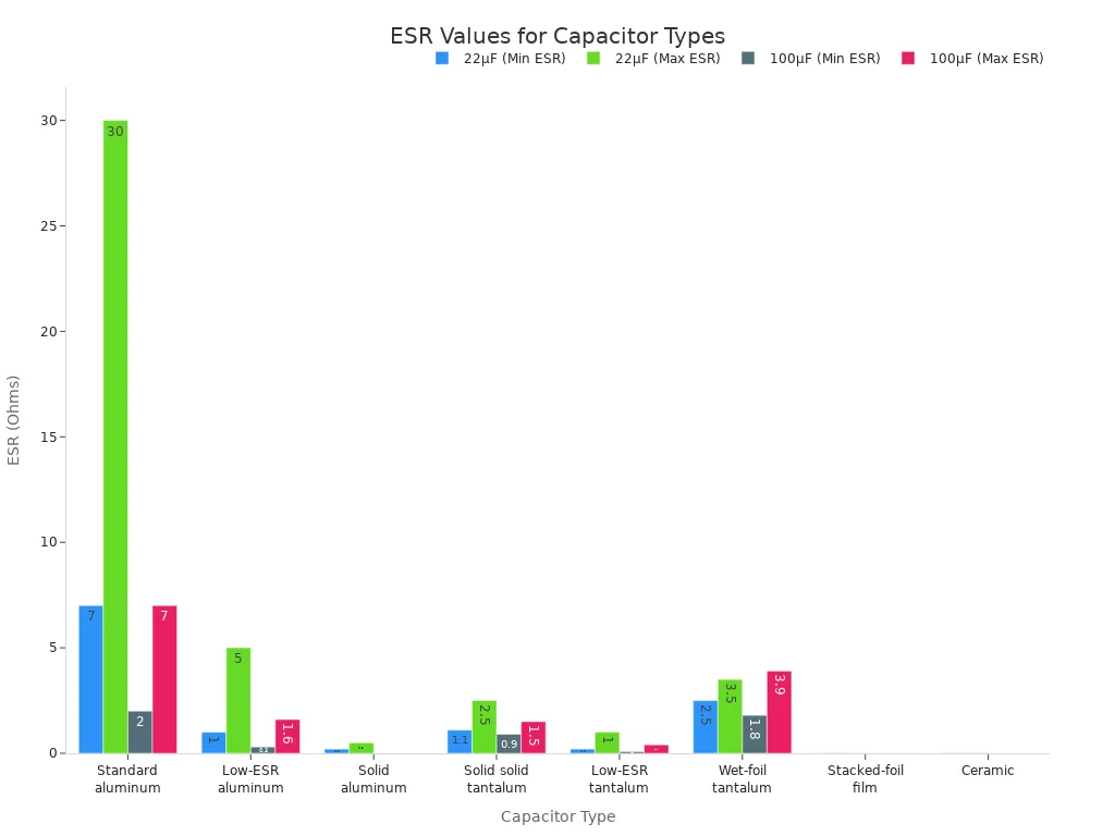
This chart illustrates the wide range of ESR values across different capacitor types. Ceramic capacitors, for example, typically exhibit very low ESR, often below 0.015 Ohms. This makes them ideal for high-frequency applications where minimizing losses is paramount.
Leakage Current: The Unwanted Drain
Leakage current refers to the small, unwanted current that flows through the dielectric material of a capacitor when a voltage applies across its terminals. Ideally, a capacitor blocks DC current entirely. However, no dielectric is a perfect insulator. This characteristic represents an inefficiency, as the capacitor slowly discharges itself.
Several factors contribute to leakage current:
-
Dielectric Absorption: The dielectric material retains some charge after discharge, leading to a gradual leakage current.
-
Defects within the Dielectric Material: Imperfections like voids or contaminants create conductive channels, allowing current to flow through the dielectric.
-
Electrolyte Leakage: In electrolytic capacitors, leakage of electrolyte due to harsh conditions can weaken the capacitor and increase leakage current.
-
Aging and Environmental Factors: Degradation of materials from temperature fluctuations, humidity, or chemicals compromises insulation, increasing leakage.
-
Voltage and Frequency Dependence: Higher frequencies or voltages can increase leakage current due to factors like dielectric polarization.
-
Absorption of Moisture: Hygroscopic dielectric materials absorb moisture, increasing their conductivity and leading to higher leakage currents.
-
Effects of Temperature: Rising temperatures can alter energy levels of flaws in the dielectric, increasing its conductivity and leakage current.
-
Voltage Overstress: Applying a voltage higher than the capacitor’s rated working voltage can stress the dielectric, causing breakdowns or flaws that result in increased leakage.
Minimizing leakage current is important for applications requiring long-term charge retention or low power consumption.
Temperature Coefficient: Performance Stability
The temperature coefficient (TC or α) quantifies how a capacitor’s capacitance changes with temperature. Engineers express it in parts per million per degree Celsius (ppm/°C). A low ppm/°C value signifies superior temperature stability. This is critical for applications demanding precise and consistent capacitance values across varying operating temperatures.
Different capacitor types exhibit varying temperature coefficients. For instance, ceramic capacitors often have a positive TC. Polyester and polypropylene film capacitors typically have low and negative TCs. This makes them suitable for stable capacitance applications. In precision circuits such as timing circuits, filters, and oscillators, capacitors with low and stable temperature coefficients are preferred. They ensure accurate performance. Manufacturers provide temperature coefficient specifications in datasheets. Engineers must consult these to select appropriate capacitors for their applications, especially considering the expected operating temperature range. This characteristic ensures the capacitor maintains its intended capacitance even when temperatures fluctuate.
Capacitor Datasheet Explained: Your Blueprint
Engineers often consider a capacitor datasheet the blueprint for a capacitor. This technical document provides all the essential information about a specific capacitor model. It details its electrical, mechanical, and environmental properties. Understanding how to read and interpret a datasheet is crucial for selecting the right capacitor for any electronic design. A datasheet empowers designers to make informed decisions, ensuring circuit reliability and performance.
Navigating a Datasheet Layout
A typical capacitor datasheet follows a structured layout. This layout helps users quickly find the information they need. Most datasheets begin with a general description of the capacitor. This section often includes its type, construction, and primary applications. Following this, engineers find detailed electrical characteristics. These characteristics include capacitance, voltage ratings, and tolerance. Mechanical data, such as dimensions and mounting options, usually appears next.
Tip: Always pay close attention to sections detailing environmental conditions and reliability data. These sections provide crucial insights into how the capacitor performs under various temperatures, humidity levels, and operational stresses. They help predict the capacitor’s lifespan and stability in real-world applications.
Further sections might cover packaging information, ordering codes, and application guidelines. Familiarity with this general structure makes navigating any capacitor datasheet much more efficient.
Identifying Key Parameters
When reviewing a capacitor datasheet, engineers must first identify several critical parameters. These parameters define the capacitor’s fundamental behavior and suitability for a given circuit.
-
Capacitance: This value defines the capacitor’s ability to store and release electrical charge. It is the most basic of all capacitor characteristics.
-
Breakdown Voltage: This parameter specifies the maximum voltage the dielectric material can withstand before failure. It is crucial for operational safety.
-
Q Factor (Quality Factor): Essential for AC circuits, the Q factor indicates the capacitor’s efficiency. It represents the ratio of reactance to equivalent series resistance (ESR).
-
Reactance and Impedance: These parameters describe the capacitor’s opposition to current changes. They are vital for understanding its AC behavior.
-
Parasitic Inductance: This refers to unintended inductance. It can reduce the Q factor, especially at higher frequencies.
-
Equivalent Series Resistance (ESR): This represents the unintended resistive property. It causes energy loss as heat and impacts efficiency, particularly in high-frequency applications. Low ESR is often preferred for decoupling.
These key capacitor characteristics help engineers quickly assess if a capacitor meets the initial requirements of their design.
Common Datasheet Symbols & Abbreviations
Capacitor datasheets use many symbols and abbreviations. Understanding these shorthand notations is essential for interpreting the data correctly. Manufacturers use these to condense complex information into a concise format.
|
Symbol/Abbreviation |
Meaning |
|---|---|
|
C |
Capacitance |
|
V_R |
Rated Voltage |
|
ESR |
Equivalent Series Resistance |
|
ESL |
Equivalent Series Inductance |
|
TC |
Temperature Coefficient |
|
DF |
Dissipation Factor |
|
IR |
Insulation Resistance |
|
µF, nF, pF |
Microfarad, Nanofarad, Picofarad |
This table provides a glimpse into the common language of a capacitor datasheet. Familiarizing oneself with these terms significantly speeds up the datasheet review process. It ensures accurate comprehension of the capacitor’s performance specifications.
Interpreting Datasheet Examples
Interpreting a capacitor datasheet involves more than just reading numbers. It requires understanding how different parameters interact and affect circuit performance. For example, a designer might look for a capacitor with a specific capacitance for a filter circuit. They would then check its voltage rating to ensure it safely handles the circuit’s maximum voltage. Next, they would examine the tolerance to see if the capacitance variation is acceptable for the filter’s precision.
Consider a power supply application. Here, a low ESR is paramount to minimize power loss and heat generation. The datasheet will provide ESR values, often at different frequencies. The designer must ensure the selected capacitor’s ESR is low enough for the ripple current expected in the power supply. The temperature coefficient also plays a role. It indicates how stable the capacitance remains across the operating temperature range. This comprehensive approach to reading a capacitor datasheet explained how engineers select the optimal component. It ensures the circuit functions reliably under all specified conditions.
By carefully analyzing all these characteristics, engineers can confidently choose the right capacitor. This prevents potential issues and optimizes circuit performance.
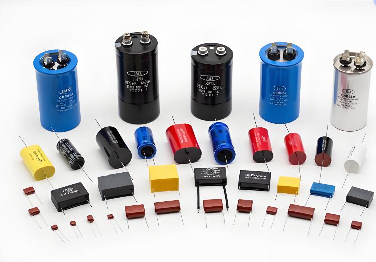
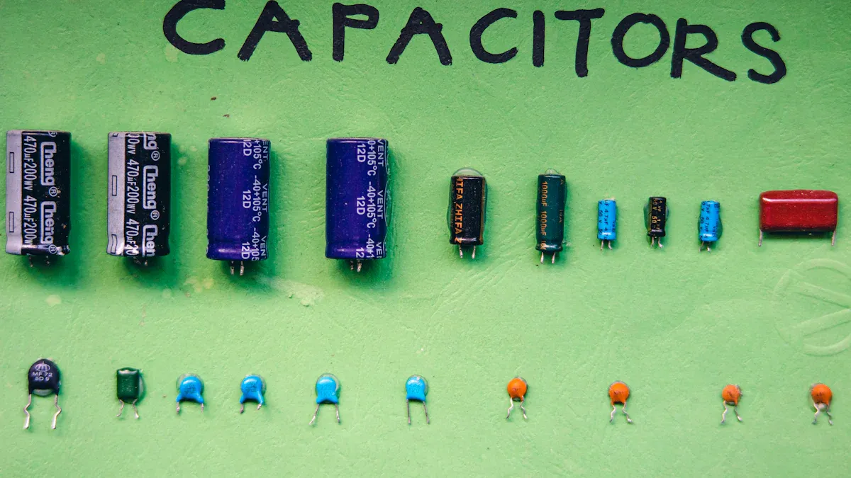
Types of Capacitors and Their Applications
Different electronic circuits require specific capacitor types. Each type offers unique characteristics and suits particular applications. Understanding these differences helps engineers select the best component.
Ceramic Capacitors: Versatile & High-Frequency
Ceramic capacitors are small and inexpensive. They offer excellent high-frequency performance. Engineers often use them for decoupling and filtering. A common example is the “101 capacitor,” which means 100pF. This small capacitor is very versatile.
Electrolytic Capacitors: High Capacitance Needs
Electrolytic capacitors provide high capacitance values. They are suitable for power filtering and energy storage. These capacitors come in different material types, like aluminum and tantalum. Aluminum electrolytic capacitors are common. Tantalum electrolytic capacitors are smaller. They have different material properties.
|
Feature |
Electrolytic Capacitors |
Other Types (Ceramic, Super) |
|---|---|---|
|
Capacitance Range |
Medium to High (µF to mF) |
Low (pF to µF) for Ceramic; Very High (Farads) for Super |
|
Size/Form Factor |
Larger, cylindrical |
Small and compact for Ceramic; Varies, often larger for Super |
|
Polarization |
Polarized |
Non-polarized for Ceramic and Super |
|
Lifespan |
Shorter, depends on usage and temperature |
Long for Ceramic; Very long for Super |
Electrolytic capacitors offer high capacitance values. They are efficient in terms of capacitance per unit volume. However, they are polarized components. This means they require correct connection to prevent damage. Their electrolyte can dry out, which reduces lifespan. This happens especially at higher temperatures. They also have higher Equivalent Series Resistance (ESR) and Equivalent Series Inductance (ESL). These factors can affect performance at high frequencies.
Tantalum Capacitors: Compact & Stable
Tantalum capacitors are compact. They offer stable performance. Engineers use them in applications where space is limited.
-
Consumer Electronics: They appear in smartphones, tablets, and laptops. They provide power smoothing and noise reduction.
-
Medical Devices: They are in pacemakers and hearing aids. Their long lifespan ensures uninterrupted performance.
-
Aerospace and Defense: They are utilized in aircraft and satellites. They handle extreme temperatures and harsh conditions. Tantalum capacitors store significant electrical charge in a small package. Their stable tantalum oxide dielectric layer ensures consistent performance. This makes them preferred for precision and safety.
Film Capacitors: Precision & Reliability
Film capacitors offer precision and reliability. Engineers use them in audio circuits and timing applications. They maintain stable capacitance across temperature changes. This capacitor type is known for its low tolerance.
Supercapacitors: High Energy Storage
Supercapacitors store much energy. They are useful for quick power bursts. They bridge the gap between traditional capacitors and batteries. This capacitor type offers very high capacitance.
Selecting the Right Capacitor Type
Choosing the right capacitor involves many factors. Engineers consider the required capacitance value. They also look at the voltage rating. The specific capacitor characteristics are crucial.
-
Capacitance Value (pF): Determine the required capacitance value for your circuit.
-
Voltage Rating (V): Select a capacitor with a voltage rating higher than the maximum expected voltage.
-
Capacitor Type: Choose based on application requirements. Consider the advantages and limitations of each type.
-
Temperature Stability: Ensure the capacitor withstands the operating temperature range.
-
Tolerance: Select a capacitor with a tolerance that meets accuracy requirements.
-
Frequency Response: Consider the capacitor’s frequency characteristics.
-
Size and Package: Choose a capacitor that fits within the available space.
-
Reliability and Quality: Select capacitors from reputable manufacturers.
Troubleshooting Capacitor Issues
Capacitors are vital components. Sometimes, they fail. Understanding common issues helps engineers fix circuits.
Recognizing Common Capacitor Failures
Engineers often see signs when a capacitor fails. Visual symptoms include a bulging or dome shape on the capacitor. Leaking electrolyte fluids also indicate a problem. Burn or scorch marks on the capacitor itself are clear signs of failure. Electrical symptoms can also appear. An AC unit might fail to turn on. It might turn on but not stay running. Weak cooling or clicking noises from the AC can point to a faulty capacitor. Unexplained high energy bills also suggest an issue.
Ceramic capacitors have specific failure modes. Breakdown can occur at the electrode edge due to material issues. This appears as pinholes or cracks. Damage along the ceramic chip’s edge happens from surface stains or impurities. This causes arcs or bursts. Breakdown within the electrode occurs from poor material compactness or cracks. Humidity can cause ceramic capacitor failure by lowering insulation. Silver ion migration, common in silver electrode capacitors, leads to short circuits. High temperatures also cause breakdown. Mechanical stress can fracture laminated ceramic capacitors.
Impact of Incorrect Selection
Choosing the wrong capacitor creates problems. Exceeding a capacitor’s rated voltage by a small amount causes capacitance to drop. A large voltage overload can break down the ceramic material. This leads to a short circuit between the metal plates. Operating a capacitor near its rated voltage or with DC bias significantly reduces its capacitance. This affects circuit operation and causes non-linear performance. Fast voltage transients, even within voltage limits, degrade ceramic materials. This shortens the capacitor’s life.
Basic Troubleshooting Steps
Engineers use specific methods to find faulty capacitors. Burn-in testing, also called voltage conditioning, involves stressing capacitors with high voltage and temperature. This identifies defects. Technicians monitor current leakage during burn-in. They check for leakage under stress. Comparing electrical properties before and after burn-in helps evaluate reliability. Engineers measure capacitance, dissipation factor, and insulation resistance. Failure mode analysis reveals issues like loss of resistivity or degradation of a capacitor’s performance.
This guide explored the fundamental nature of a capacitor, detailing its core function and various types. We examined key capacitor characteristics like capacitance, voltage rating, and ESR. The guide also provided a clear capacitor datasheet explained section, helping readers interpret crucial specifications. Understanding these different characteristics is essential for successful electronics projects and effective troubleshooting. Apply this newfound knowledge to confidently select the right capacitor for your designs. Continue learning about each capacitor type. Mastering fundamental components like the capacitor empowers innovation in electronics.
What is the primary function of a capacitor?
A capacitor stores electrical energy in an electric field. It releases this energy when needed. This function makes the component essential for filtering, timing, and energy storage in many electronic circuits.
Why is voltage rating important for a capacitor?
The voltage rating indicates the maximum voltage a capacitor can safely handle. Exceeding this limit can damage the component and the circuit. Engineers must select a capacitor with a higher voltage rating than the circuit’s operating voltage.
What does “capacitance” mean?
Capacitance measures a capacitor’s ability to store an electrical charge. A higher capacitance value means the component stores more energy for a given voltage. This fundamental capacitance is crucial for circuit design.
Can engineers use any capacitor in any circuit?
No, engineers must select the correct capacitor type for each circuit. Different applications require specific characteristics, such as capacitance, voltage rating, and ESR. Using the wrong component can lead to poor performance or failure.
What happens if a capacitor fails?
A failed capacitor can cause various circuit problems. These include device malfunction, reduced performance, or complete circuit failure. Visual signs like bulging or leaking often indicate a faulty component. Understanding capacitance helps diagnose issues.
See Also
Coilcraft XPL2010: High-Performance Inductors for Optimal VRM/VRD Design
Achieving Excellence: Innovation, Quality, and Trends in Electronic Components
MC9S12DJ256MFUE: Automotive Electronics’ Core, Explored and Implemented Practically
Essential Programming Guide for MC9S12XD256 Microcontroller Development
STM32F030C8T6: Your Step-by-Step Guide to Smart Home Automation