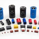

Capacitors are fundamental electronic components that store electrical charge, playing vital roles in filtering, timing, and energy storage within circuits. These essential devices come in fixed and variable forms, and they can be polarized or non-polarized. Choosing the right capacitor type is critical for circuit performance, reliability, and cost. This guide explores three main types of capacitors: electrolytic capacitors, ceramic, and film. Each of these types of capacitors possesses unique strengths and weaknesses. Understanding these differences is key to effective capacitor types and selection. This guide will provide practical insights on how to choose the right capacitor, focusing on critical Capacitor Selection Criteria.
Key Takeaways
-
Capacitors store electrical charge. They are important parts of electronic circuits. Choosing the right type helps circuits work well.
-
Electrolytic capacitors store a lot of charge. They are good for power supplies. They must be put in the right way because they have a positive and negative side.
-
Ceramic capacitors are small and work well with fast signals. They do not have a positive or negative side. They are good for cleaning up noise in power.
-
Film capacitors are very steady and precise. They can fix themselves if they get a small problem. They are good for exact timing and audio circuits.
-
Always check a capacitor’s voltage, temperature, and how much resistance it has inside. This helps your circuit last longer and work better.
Exploring Electrolytic Capacitors
Function and Construction
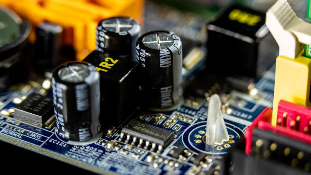
Electrolytic capacitors are a type of capacitor known for their high capacitance values. They achieve this by using an electrolyte, which acts as one of the plates, and a very thin oxide layer as the dielectric. This construction allows for a large capacitance in a relatively small volume. These capacitors are crucial for many electronic applications. Their ability to store significant electrical charge makes them indispensable.
Polarity and Key Ratings
Electrolytic capacitors are polarized components. This means they must be installed correctly with respect to voltage polarity. Connecting them in reverse can cause damage or even explosion. Key ratings include capacitance (measured in microfarads, µF), voltage rating (the maximum DC voltage they can safely handle), and temperature range. Designers must always ensure the applied voltage does not exceed the capacitor’s rating. Understanding these ratings is vital for proper circuit function.
ESR and Frequency Response
Equivalent Series Resistance (ESR) is a critical parameter for electrolytic capacitors. ESR represents the internal resistance of the capacitor. A lower ESR indicates better performance, especially in power supply applications. High ESR can lead to increased power loss and heat generation. Electrolytic capacitors generally perform well at lower frequencies. Their impedance increases at higher frequencies due to parasitic inductance, limiting their effectiveness in high-frequency circuits. This characteristic affects their role in filtering.
Pros, Cons, and Common Uses
Electrolytic capacitors offer high capacitance density, making them suitable for applications requiring significant energy storage. They are excellent for smoothing voltage ripples in power supplies. This smoothing action helps maintain a stable DC voltage. However, these capacitors have several disadvantages. They are polarized, have a limited lifespan, and their performance degrades over time. Common failure modes for electrolytic capacitors include:
-
Explosion due to reverse installation.
-
Explosion due to exceeding maximum forward or reverse voltage.
-
Heating and eventual failure caused by ripple current, especially in switching power supply outputs.
-
Failure, potentially short circuiting and producing smoke, due to vibration and shock loading. A Panasonic datasheet, for example, lists these common failure modes for electrolytic capacitors with wet electrolytes. These issues are representative of problems with most suppliers’ electrolytic capacitors. Designers often use electrolytic capacitors for DC bus filtering, audio coupling, and power supply smoothing. These capacitors are essential for many power management circuits.
Understanding Ceramic Capacitors
Function and Construction
Ceramic capacitors use ceramic materials as their dielectric. These ceramics are typically mixtures of finely ground granules of para-electric or ferro-electric materials. Manufacturers combine these with other substances to achieve specific electrical characteristics. Common raw materials include alumina (aluminum oxide) and titanium oxide. Paraelectric titanium dioxide (rutile) was among the first ceramic dielectrics used. Engineers valued it for its linear temperature dependence of capacitance, which was beneficial for temperature compensation in resonant circuits. It also served as a replacement for mica capacitors.
Non-Polarity and Dielectric Types
Unlike electrolytic capacitors, ceramic capacitors are non-polarized. This means engineers can install them in any orientation in a circuit. This simplifies design and assembly. Ceramic capacitors are categorized into different classes based on their dielectric materials.
|
Class |
Definition |
Materials |
|---|---|---|
|
Class I |
Ceramic capacitor with high stability and low loss |
TiO2 with additives like Zn, Zr, Nb, Mg, Co |
|
Class II |
Ceramic capacitor with high volumetric efficiency |
Al2O3, magnesium silicate, aluminum silicate |
|
Class III |
High volumetric efficiency than EIA class—II and lower temperature range (10°C–50°C) |
BaTiO3 |
The dielectric type significantly influences the temperature stability of ceramic capacitors. C0G (Class I) dielectrics offer superior stability. They have low relative permittivity, making them suitable for precision applications. In contrast, X5R and X7R (Class II) dielectrics use ferroelectric barium-titanate ceramics. These provide high capacitance density but exhibit non-linear behavior with temperature.
|
Dielectric Type |
Class |
Relative Permittivity |
Temperature Range |
Capacitance Tolerance |
Key Characteristics |
|---|---|---|---|---|---|
|
C0G (NP0) |
I |
Low (≈ 30) |
Wide (excellent stability) |
Excellent |
Excellent stability, preferred for precision |
|
X5R |
II |
High (2,000 – 4,000) |
–55°C to +85°C |
±15% (above 85°C drift may exceed) |
High capacitance density, non-linear behavior |
|
X7R |
II |
High (2,000 – 4,000) |
–55°C to +125°C |
±15% |
High capacitance density, relatively flat response |
|
X8L |
II |
High |
–55°C to +150°C |
±15% |
Extended high-temperature range |
X7R capacitors maintain a relatively flat response up to 125°C. They have a temperature coefficient of capacitance (TCC) of approximately -400 ppm/°C. X5R capacitors follow a similar model but are only guaranteed up to 85°C. Beyond this, their capacitance drift can exceed ±15%. For environments exceeding 85°C, X7R is recommended. The ‘R’ in X7R signifies a temperature coefficient of ±15% across its operating range of –55°C to +125°C. X5R is guaranteed to 85°C. Newer X8L capacitors extend this range to +150°C with a ±15% tolerance.
Stability and Performance
Ceramic capacitors offer excellent high-frequency performance. However, designers must consider voltage coefficient and microphonics. The voltage coefficient describes how capacitance changes with applied voltage. Some ceramic types, especially Class II, show a significant decrease in capacitance as voltage increases. Microphonics, or piezoelectric effects, occur when mechanical stress on the capacitor generates a voltage, or vice versa. This can introduce noise in sensitive analog circuits.
Pros, Cons, and Common Uses
Ceramic capacitors are compact, cost-effective, and offer good high-frequency response. Their non-polarity simplifies circuit design. However, some types exhibit capacitance variation with temperature and voltage. They can also suffer from microphonics.
Common uses for ceramic capacitors include:
-
Decoupling: They reduce noise in the power supply and remove voltage variances. Engineers place them close to IC power pins on a PCB to provide local charge storage.
-
Smoothing: They even out signal fluctuations and voltage waveforms for consistent current.
-
Filtering signals: Used with inductors and resistors, they create filters that block unwanted frequencies. This is common in audio systems to eliminate interference.
Class 1 ceramic capacitors are ideal for precision applications. These include oscillators, timers, and analog-to-digital converters. Class 2 ceramic capacitors are commonly chosen for non-critical decoupling, coupling, and bypassing applications.
Delving into Film Capacitors
Function and Construction
Film capacitors use a thin plastic film as their dielectric material. Manufacturers typically metallize this film on one or both sides. They then wind these layers into a cylindrical shape. This construction provides excellent electrical properties. Common dielectric materials for these capacitors include:
-
Polypropylene (PP)
-
Polyester (PET)
-
Polycarbonate
-
Polystyrene
-
Polytetrafluoroethylene (PTFE)
-
Polyethylene naphthalate (PEN)
-
Polyphenylene sulphide (PPS)
-
Polyimide
-
Paper
The choice of film material determines the capacitor’s characteristics, such as temperature stability and loss factor.
Non-Polarity and Key Ratings
Film capacitors are non-polarized, similar to ceramic capacitors. This means engineers can install them in a circuit without concern for voltage direction. Key ratings include capacitance, voltage rating, and tolerance. Film capacitors often boast very tight tolerances, sometimes as low as ±1%. This precision makes them suitable for demanding applications. Their voltage ratings can also be quite high, making them useful in power electronics.
Stability and Self-Healing
Film capacitors offer excellent long-term stability and low dielectric absorption. This makes them ideal for precision circuits. A unique benefit of metallized film capacitors is their self-healing property. When a localized dielectric breakdown occurs, the metallization layer around the fault vaporizes. This isolates the defect without compromising the overall dielectric system. The capacitor continues to function normally. This mechanism prevents catastrophic failures, unlike other capacitor types. However, repeated self-healing events can gradually reduce capacitance and insulation resistance. This can impact reliability in some high-precision applications.
Pros, Cons, and Common Uses
Film capacitors excel in precision and stability. They offer consistent capacitance and low dielectric loss. This makes them suitable for precision timing and resonant circuits. For example, audio circuits use film capacitors for maintaining linearity and low distortion. Polypropylene and polystyrene types are specifically used in audio crossovers and equalizers. They are also chosen for high-frequency filters due to their stability across temperature and frequency. Film capacitors provide excellent stability, low losses, and long operational life. This makes them requisite for consistent, long-term performance in both AC and DC applications. They are generally larger and more expensive than ceramic capacitors for the same capacitance value. They also offer less energy storage density than electrolytic capacitors.
Essential Parameters for Capacitor Selection
Designers must consider several critical parameters when selecting capacitors for any electronic circuit. These parameters directly influence circuit performance, reliability, and overall cost. Understanding each factor helps engineers make informed decisions for optimal design.
Capacitance and Tolerance
Capacitance measures a capacitor’s ability to store an electrical charge. Engineers specify capacitance in Farads (F), though microfarads (µF), nanofarads (nF), and picofarads (pF) are more common in practice. The required capacitance value depends entirely on the circuit’s function, whether it involves filtering, timing, or energy storage.
Tolerance indicates the permissible deviation from the nominal capacitance value. A capacitor with a 100 nF nominal value and a ±10% tolerance can have an actual capacitance between 90 nF and 110 nF. Different capacitor types offer varying tolerance levels. For example, precision applications often require very tight tolerances.
|
Capacitor Type |
Tolerance Range |
|---|---|
|
Ceramic capacitor class 1 (NP0) |
±0.5% |
|
Ceramic capacitor class 2 (X7R) |
±15% |
|
Ceramic capacitor class 2 (Y5V) |
+22% / −82 % |
|
Film capacitor (Polypropylene) |
±2.5% |
|
Film capacitor (Polyester) |
+5% |
|
Film capacitor (Polyphenylene sulfide) |
±1.5% |
|
Film capacitor (Polyethylene naphthalate) |
±5% |
|
Metallized paper capacitor |
±10% |
|
Aluminum electrolytic capacitor |
±20% |
|
Tantalum electrolytic capacitor |
±20% |
Designers must select a tolerance suitable for the application. A wide tolerance might be acceptable for power supply decoupling, but precision timing circuits demand much tighter control over capacitance.
Voltage Rating and Derating
The voltage rating (VR) specifies the maximum DC voltage a capacitor can safely withstand without breaking down. Exceeding this rating can lead to catastrophic failure. However, simply choosing a capacitor with a voltage rating equal to the circuit’s maximum voltage is often insufficient for long-term reliability.
Voltage derating involves selecting a capacitor with a voltage rating significantly higher than the maximum expected operating voltage. This practice enhances reliability and extends the capacitor’s lifespan. For ceramic capacitors, a common rule suggests derating the voltage rating by at least 25% as a standard practice. In environments with voltage ripple effects, this derating should increase to at least 50%. The component’s maximum rated voltage should be at least double the maximum voltage applied during normal operations.
For a capacitor family, an 80% voltage derating is recommended for ambient temperatures from -55°C to 105°C. For instance, a 35 Vdc rated capacitor should not exceed 28 Vdc (0.8 x 35 Vdc). Component vendors often include derating guidelines in datasheets or separate documents. The Kemet derating information cited is from KEMET Organic Capacitor (KO-CAP (R) —Industrial, T521 High Voltage Polymer Electrolytic, 12.5 – 75 VDC. Additionally, the US Navy Derating Guideline, SD-18, and other guidelines like SMC Standard SMC-S-010, NASA’s EEE-INST-002, IPC-9592, and Mil-Hdbk-338 provide specific guidance for various applications, such as power conversion devices or space-borne equipment.
Different capacitor types and applications require specific derating strategies:
-
Tantalum MnO2 capacitors: Engineers recommend a 50% derating in high current surge applications. These include the input side of DC/DC converters or direct connections to a battery. For other applications, such as coupling, timing, or DC/DC output, a 20% derating is typical.
-
Tantalum polymer capacitors: A 10% derating applies to all circuits for capacitors with ratings up to 10V. For capacitors rated above 10V, a 20% derating is necessary for all circuits.
These derating guidelines typically apply up to 105°C. Additional derating may be necessary for temperatures up to 125°C.
Consider these examples for tantalum polymer capacitors:
-
125°C device with tantalum polymers: A 20% voltage derating is recommended for 16V tantalum polymer capacitors. An additional 33% derating is needed at 125°C. This means a 16V capacitor is not suitable for 125°C operation. A higher rated 20V tantalum polymer capacitor is required to apply a maximum of 10.7V.
-
105°C device with tantalum polymers: No temperature derating is needed at 105°C. Only the 20% derating for all circuits applies. A 16V tantalum polymer capacitor can be used up to 12.8V across the entire 105°C temperature range.
-
Tantalum MnO2 capacitors: These require 50% derating for hard surge current applications. This means 25V capacitors must be used. For 125°C devices, the 33% temperature derating is covered by the 50% surge current derating. 16V tantalum MnO2 capacitors can be used in non-surge critical applications with a 20% derating.
Follow these steps for effective voltage derating:
-
Identify capacitor type and rating: Determine the capacitor’s rated voltage, temperature, and technology (e.g., MLCC, tantalum, electrolytic, film).
-
Apply voltage derating: Reduce the applied voltage by the recommended percentage. For example, use 80% of the rated voltage for general applications or 50% for high surge MnO₂ tantalum capacitors.
-
Consider temperature derating: For high operating temperatures (e.g., 125°C), apply additional derating as specified by manufacturer guidelines.
-
Account for surge current limitations: For circuits with high inrush or surge currents, select capacitors with higher voltage ratings or apply stricter derating rules based on capacitor technology.
-
Verify reliability and compliance: Ensure the derating strategy meets application requirements, improves reliability, and complies with manufacturer recommendations.
|
Temperature Range |
Voltage Rating (VR) |
Max Recommended Steady State Voltage |
Max Recommended Transient Voltage (1 ms – 1 μs) |
|---|---|---|---|
|
-55°C to 105°C |
12.5 V ≤ VR ≤ 75 V |
80% of VR |
VR |
|
105°C to 125°C |
12.5 V ≤ VR ≤ 75 V |
54% of VR |
67% of VR |
ESR, ESL, and Ripple Current
Equivalent Series Resistance (ESR) represents the total internal resistance of a capacitor. It includes the resistance of the leads, electrodes, and dielectric material. Equivalent Series Inductance (ESL) represents the parasitic inductance within the capacitor structure. Both ESR and ESL are critical for high-frequency applications.
In high-power or high-frequency applications, considering ESR in impedance calculations is crucial for maintaining operational efficiency and preventing failures. Low-ESR multi-layer ceramic capacitors (MLCCs) are often the best choice for these scenarios. They minimize capacitor losses, enhance power supply efficiency and stability, and reduce output ripple voltage. A capacitor with low ESR dissipates less heat, preventing overheating and potential failure. This is vital in circuits where any additional resistance can negatively impact performance and reliability.
High ESR in capacitors leads to significant heat generation, calculated as I²R (ripple current squared times ESR). If this heat exceeds the component’s dissipation capability, especially in small capacitors used in high-frequency switchmode supplies (e.g., 50 kHz), it can cause premature failure. While the ESR zero can sometimes aid stability in a power supply control loop, it comes at the cost of increased output ripple. Therefore, for applications with high ripple current where the ESR zero isn’t critical for stability, low-ESR capacitors are generally preferred to manage heat and ripple effectively.
In high-frequency switching power supplies, high Equivalent Series Resistance (ESR) in capacitors leads to increased power loss, which dissipates as heat. This heat reduces the overall efficiency of the circuit and can shorten the lifespan of the capacitor and surrounding components. For example, a capacitor with an ESR of 100 mΩ carrying a 1 A ripple current at 100 kHz will dissipate 0.1 W of power as heat. Furthermore, high ESR directly contributes to larger output voltage ripple, causing instability in sensitive electronic devices. Low-ESR capacitors, such as ceramic types, are preferred in these applications to mitigate these negative effects by minimizing power loss and heat generation.
ESR also influences the self-resonant frequency (SRF) of a capacitor. At the SRF, the capacitive and inductive effects cancel each other out. This results in the lowest impedance, which is primarily determined by the ESR. Beyond the SRF, the capacitor’s behavior shifts, acting more like an inductor due to Equivalent Series Inductance (ESL). This can be problematic in high-frequency applications.
Ripple current refers to the AC current component flowing through a capacitor, especially in power supply filtering. High ripple currents combined with high ESR generate significant heat, potentially leading to capacitor failure. Designers must select capacitors with appropriate ripple current ratings for their applications.
Temperature and Frequency
Temperature significantly impacts capacitor performance and lifespan. Operating capacitors outside their specified temperature range can lead to degradation or failure.
Higher temperatures accelerate chemical reaction rates within electrolytic capacitors. This typically doubles the rate for every 10°C rise. This leads to accelerated changes, including decreasing capacitance and increasing ESR (tan d). This occurs primarily due to the gradual evaporation of the electrolyte through the capacitor seal. The change in Equivalent Series Resistance (ΔESR) measures electrolyte loss and is experimentally shown to be temperature-dependent. Degradation of capacitor characteristics, such as capacitance reduction and ESR increase, occurs more rapidly at higher temperatures. Specifically, capacitance reduction (ΔCap) increases proportionally to electrolyte loss, while ESR increases even more rapidly.
The Equivalent Series Resistance (ESR) of electrolytic capacitors is highly temperature-dependent. The electrolyte’s conductivity is a major contributor to ESR. As the fluid electrolyte is lost over time due to vaporization and diffusion, the amount of conducting material reduces. This increases the ESR and reduces capacitance. This ‘drying out’ process accelerates at higher temperatures. However, in aluminum electrolytics, ESR can initially fall as the temperature increases. This means its effects reduce as assemblies warm up. But the long-term drying out due to heat will increase ESR.
Temperature significantly impacts the capacitance of electrolytic capacitors. Increased operating temperatures accelerate the evaporation of the electrolyte. This directly reduces the capacitor’s ability to hold charge, thereby decreasing its capacitance. This drying out process also leads to a steady decline in capacitance over time.
Frequency response describes how a capacitor behaves across different frequencies. All capacitors exhibit parasitic inductance (ESL) and resistance (ESR). At low frequencies, a capacitor acts primarily as a capacitor. As frequency increases, ESL becomes more dominant, eventually causing the capacitor to behave like an inductor above its self-resonant frequency. Designers must consider the operating frequency range of their circuit when choosing capacitor types and selection.
Size, Cost, and Reliability
Physical size is a practical constraint in many modern electronic designs, especially for compact devices. Different capacitor types offer varying capacitance densities. Electrolytic capacitors provide high capacitance in a relatively small package, but ceramic capacitors are often smaller for lower capacitance values. Film capacitors tend to be larger for comparable capacitance.
Cost is always a significant factor in product development. The cost differences between various capacitor types can be substantial.
-
Electrolytic capacitors are characterized by their low cost.
-
Ceramic capacitors are more expensive than electrolytic capacitors.
-
For large capacitance values (e.g., >100uF), ceramic capacitors become significantly more expensive compared to electrolytic capacitors.
-
Ceramic capacitors offer higher performance at a lower cost compared to electrolytic capacitors.
-
Film capacitors tend to be more expensive than other types, such as ceramic capacitors.
-
Ceramic capacitors are generally low cost.
-
Electrolytic capacitors range from low to medium cost.
Reliability and lifespan are crucial for long-term product performance.
-
Ceramic Capacitors: These generally last longer than electrolytic capacitors. They often operate for several decades under normal conditions due to their reliability and resistance to aging.
-
Tantalum Electrolytic Capacitors: Engineers can expect these to last between tens of thousands to 50,000 hours, depending on conditions.
-
Aluminum Electrolytic Capacitors: These have a lifespan varying between 2,000 and 10,000 hours. Factors like electrolyte quality, construction, temperature, ripple currents, and voltage stress influence their lifespan.
The choice of capacitor types and selection involves balancing these parameters to meet the specific requirements of the application.
Capacitor Types and Selection: A Practical Guide
Choosing the correct capacitor for an electronic circuit is a critical decision. Engineers must understand the strengths and weaknesses of different types of capacitors to ensure optimal performance and reliability. This section provides a practical guide for capacitor types and selection, offering a framework for making informed choices and avoiding common design pitfalls.
Comparing Different Types of Capacitors
Engineers encounter various types of capacitors, each with unique characteristics. A comparative overview helps in understanding their primary applications.
|
Feature / Type |
Electrolytic Capacitors |
Ceramic Capacitors |
Film Capacitors |
|---|---|---|---|
|
Capacitance Range |
High (µF to F) |
Low to Medium (pF to µF) |
Medium (nF to µF) |
|
Polarity |
Polarized |
Non-Polarized |
Non-Polarized |
|
ESR / ESL |
High ESR, Moderate ESL |
Very Low ESR, Very Low ESL |
Low ESR, Low ESL |
|
Frequency Response |
Low-frequency applications |
High-frequency applications |
Good across wide range, low loss at high frequencies |
|
Temperature Stability |
Moderate (degrades with heat) |
Varies (C0G excellent, X5R/X7R moderate) |
Excellent |
|
Tolerance |
Wide (±10% to ±20%) |
Varies (C0G tight, X5R/X7R wider) |
Tight (±1% to ±5%) |
|
Size |
Large for high capacitance |
Small, compact |
Medium to Large |
|
Cost |
Low to Medium |
Low to Medium |
Medium to High |
|
Self-Healing |
No |
No |
Yes (metallized film) |
|
Common Uses |
Power supply filtering, energy storage |
Decoupling, filtering, resonant circuits |
Precision timing, audio, power factor correction |
Electrolytic, paper, or plastic film capacitors are not ideal for high-frequency decoupling. Their rolled structure, consisting of metal foil separated by dielectric sheets, results in significant self-inductance. This characteristic causes them to behave more like inductors than capacitors at frequencies exceeding just a few MHz.
-
Ceramic capacitors are required for high-frequency applications. When combined with electrolytic capacitors, they are less likely to have impedance variation across frequencies.
-
Electrolytic capacitors are suitable for low-frequency applications. Their capacitance gradually decreases with increasing frequency, and loss increases sharply.
-
Film capacitors show good frequency characteristics. Their capacitance only decreases slightly with increasing frequency, and they exhibit low loss even at higher frequencies.
Selection Framework for Applications
Engineers can follow a structured approach to select the right capacitors for specific applications. This framework considers the primary function of the capacitor in the circuit.
1. Power Supply Decoupling: Decoupling capacitors are essential for stabilizing power rails and reducing noise. Engineers must consider several factors for these capacitors.
-
Self-resonant frequency: This is the point where the capacitor transitions from capacitive to inductive behavior. A lower capacitance and inductance lead to a higher resonant frequency, which is desirable. Smaller surface-mount components typically offer higher resonant frequencies due to lower parasitic inductance. For low-frequency noise, capacitor values range from 1 µF to 100 µF, while high-frequency noise requires values between 0.01 µF and 0.1 µF.
-
Equivalent series resistance (ESR) and equivalent series inductance (ESL): Decoupling capacitors must deliver current rapidly. Therefore, selecting components with low ESR and ESL is crucial. These parameters indicate minimal internal resistance and inductance, respectively, and are typically found in the component’s datasheet.
-
Package size: Smaller package sizes generally result in lower ESL. Additionally, wide geometry capacitors are preferred over standard ones due to their lower inductance. Minimizing via inductance is also important when connecting capacitors to ICs via PCB vias.
The power distribution network (PDN) type also influences capacitor selection:
-
Digital Power Distribution Network (PDN): The capacitor size is determined by the PDN’s impedance and the current demand of the switching IC. Accurate sizing and placement help reduce ripples and noise. The capacitor size can be calculated based on the current drawn during switching and the IC voltage, provided the signal bandwidth is less than the capacitor’s self-resonance frequency.
-
Analog Power Distribution Network (PDN): For analog ICs, the decoupling capacitor continuously charges and discharges to maintain stable power. Its size is determined by the IC’s current draw, which is a function of the IC voltage and frequency.
-
PDN Impedance: Decoupling capacitors reduce the overall PDN output impedance and supply charge promptly. However, they are effective only within a specific frequency range. The impedance decreases with decreasing frequency and increases with increasing frequency due to parasitic inductance. A key method for determining capacitor size involves targeting a specific PDN impedance, considering factors like voltage ripple, target PDN impedance, and target PDN voltage. Calculating the capacitance often requires iterative approaches to achieve the lowest PDN impedance across various frequency ranges. The exact capacitor values are typically specified in the IC’s datasheet.
Specific types of capacitors are best for decoupling:
-
Electrolytic capacitors (1 to 100 μF) are used for decoupling low-frequency noise and act as charge reservoirs. They should be placed close to the IC (within 2 inches). These are polarized and have relatively high leakage currents, though leakage typically does not significantly impact decoupling.
-
Ceramic capacitors are ideal for decoupling high-frequency power supply noise. Engineers connect them directly to the IC’s power pins. Capacitances of 0.1 or 0.01 μF are effective for filtering high-frequency noise due to their high resonant frequencies. They are compact, have low loss, wide temperature tolerance, low ESR/ESL, stability, and reliability. X7R types are preferred for their stable capacitance with DC bias, and NP0 (C0G) types are also used for their low dielectric constant and voltage coefficient.
-
Multilayer Ceramic (MLCC) Surface-Mount Capacitors are employed for bypassing and filtering at 10MHz or higher frequencies due to their low inductance design.
2. Precision Timing Circuits: For applications requiring precise timing, such as oscillators or filters, the choice of capacitors is crucial.
-
Component Availability: Consider the availability of capacitors in your inventory or at your supplier. Choose a standard value that is readily accessible.
-
Tolerance: Capacitors have tolerances. Choose a value that accommodates the desired precision of your timing circuit.
-
Physical Size: Larger capacitance values often result in physically larger components. Ensure that the chosen capacitor can fit within the space constraints of your circuit board or enclosure.
-
Voltage Rating: Select a capacitor with a voltage rating that exceeds the maximum voltage expected in your circuit to prevent damage.
-
Temperature Stability: Some applications may require capacitors with stable capacitance over a wide temperature range. Consider capacitors with appropriate temperature coefficients if temperature stability is crucial. Film capacitors, particularly polypropylene, are often preferred for their excellent stability in these applications.
Avoiding Common Design Pitfalls
Improper capacitor types and selection can lead to significant problems, including circuit instability or premature component failure. Engineers must be aware of common mistakes.
-
Ignoring the manufacturer’s recommended maximum ripple current rating leads to a detrimental rise in the capacitor’s temperature and shortens its lifetime.
-
Using capacitor values that are lower than calculated for the circuit can shorten the lifetime of the capacitors and the circuit, and potentially impair the circuit’s functioning.
-
Confusing the rated ripple current of the capacitor with the calculated ripple current of the circuit leads to underestimation of internal heating and a shorter capacitor lifetime.
Incorrect capacitance tolerance can lead to instability, noise, or premature failure. The dielectric material (e.g., X7R, NP0, Y5V) significantly affects circuit performance. ESR (Equivalent Series Resistance) is a critical specification that impacts circuit stability. An improper voltage rating can drastically affect circuit performance, leading to instability or premature failure. Poorly placed or selected capacitors can cause EMI, ringing, or power integrity issues, even if their datasheet specs seem perfect. Under-specifying a capacitor’s voltage, capacitance, or ESR can lead to premature failure or circuit instability. For instance, a decoupling capacitor placed too far from a microcontroller may fail to suppress high-frequency noise effectively, while a bulk capacitor with an insufficient voltage rating can cause power instability.
Engineers must carefully consider all parameters when deciding how to choose the right capacitor. This attention to detail ensures robust and reliable circuit designs.
This guide explored various types of capacitors, including electrolytic, ceramic, and film capacitors. Each of these capacitors offers unique strengths. Electrolytic capacitors excel in power filtering and energy storage. Ceramic capacitors handle high-frequency decoupling and resonant circuits. Film capacitors provide precision and stability. Selecting the right types of capacitors requires understanding specific circuit needs. No single capacitor type is universally superior. Always consider key parameters like voltage, ESR, and temperature for optimal performance and reliability of these capacitors. Apply these insights to your designs, choosing the best capacitors.
What challenges have you faced when selecting capacitors for your projects? Share your experiences and tips in the comments below!
Why are electrolytic capacitors polarized?
Electrolytic capacitors use an electrolyte to form a dielectric layer. This process creates a specific polarity for these capacitors. Reversing the voltage can damage this layer, causing the capacitors to fail. Designers must install these capacitors correctly. These are crucial components.
What makes ceramic capacitors suitable for high-frequency applications?
Ceramic capacitors have very low Equivalent Series Resistance (ESR) and Equivalent Series Inductance (ESL). These characteristics allow ceramic capacitors to respond quickly to high-frequency signals. This makes these capacitors excellent for filtering and decoupling in high-speed circuits. These capacitors are versatile components.
How do film capacitors “self-heal”?
Metallized film capacitors have a unique self-healing property. If a small breakdown occurs in the dielectric, the metallization around the fault vaporizes. This isolates the defect. The film capacitors continue to function, preventing catastrophic failure of these capacitors. These capacitors offer great reliability.
Why is voltage derating important for capacitors?
Voltage derating involves selecting capacitors with a higher voltage rating than the circuit’s maximum operating voltage. This practice significantly increases reliability and extends the lifespan of the capacitors. It prevents premature failure due to voltage stress on these critical components. These capacitors require careful selection for optimal performance.
See Also
Coilcraft XPL2010: High-Performance Inductors for Optimal VRM/VRD Design
Electronic Components: Innovation, Quality, and Future Trends for Industry Excellence
LPQ252-CEF: Unlocking Efficient Power Management Solutions for Modern Systems
SPC5605BMLL6/SPC5607BMLL6 ECUs: Powering Future Automotive Systems with Advanced Technology
M30280FAHP Microcontroller: Balancing Performance and Compliance in Medical Electronics Core