The W5500 module’s Link/ACT LEDs often fail to function when the hardware setup encounters interruptions. Incorrect wiring, mismatched configurations, or outdated firmware can disrupt the connection. For example, users working with ESP32, W5500, and power supply modules sometimes face this issue due to voltage mismatches. When the LEDs fail to light up, troubleshooting becomes essential to restore connectivity. This issue is especially common in cases involving a custom W5500 Ethernet Module – Link/ACT LEDs Not Working When RJ45 Cable is Connected? Identifying the root cause can simplify the resolution process and improve module performance.
Key Takeaways
-
Check all hardware connections to make sure pins are tight. Loose pins can stop Link/ACT LEDs from working.
-
Double-check settings like PMODE jumpers and voltage levels. Correct settings are important for the module to work well.
-
Update the firmware often to fix bugs and improve it. Updated firmware helps avoid LED problems.
-
Test the W5500 module with a working setup to find issues. This helps you see if the problem is the module or something else.
-
Use good hardware practices, like quality parts and neat PCB layouts. These steps make the module more reliable.
Custom W5500 Ethernet Module – Link/ACT LEDs Not Working When RJ45 Cable is Connected?

What Are Link/ACT LEDs?
Link/ACT LEDs are small indicators on Ethernet modules that provide real-time feedback about the network connection. The “Link” LED lights up when the module establishes a physical connection with another device through an Ethernet cable. The “ACT” (Activity) LED blinks to indicate data transmission or reception over the network. These LEDs are essential for diagnosing connectivity issues and ensuring the module operates correctly.
In custom W5500 Ethernet modules, these LEDs rely on the proper functioning of Ethernet signals. The hardware layout plays a critical role in maintaining signal integrity. For high-speed signals, improper layout practices, such as poor impedance control or the absence of solid reference planes, can degrade performance. This degradation may prevent the Link/ACT LEDs from functioning as intended, making it harder to identify connection problems.
Common Symptoms of the Issue
When the Link/ACT LEDs on a custom W5500 Ethernet module fail to work, several symptoms may appear. These include:
-
The “Link” LED remains off even after connecting an RJ45 cable.
-
The “ACT” LED does not blink during data transmission or reception.
-
The Ethernet module fails to establish a network connection despite proper wiring.
-
Intermittent connectivity issues occur, with the LEDs flickering inconsistently.
These symptoms often point to underlying issues such as incorrect hardware connections, mismatched voltage levels, or outdated firmware. In some cases, the problem may stem from the Ethernet hardware layout. Ensuring proper impedance control and using solid reference planes can help maintain signal integrity, which is crucial for the LEDs to function correctly.
By understanding these symptoms, users can identify potential causes and take appropriate steps to resolve the issue.
Troubleshooting the Link/ACT LEDs Issue

Check Hardware Connections
Proper hardware connections are essential for the Link/ACT LEDs to function correctly on the W5500 module. Users should inspect the wiring and ensure all pins are connected securely. Loose or floating pins can disrupt the module’s operation and prevent the LEDs from lighting up.
Several users have reported that issues with the CS pin often lead to LED malfunctions. For example, a floating CS pin can interfere with the eth.getIP() function, which is critical for establishing a network connection. To resolve this, users should verify that the CS pin is properly grounded or connected to the microcontroller.
The following table outlines key hardware connection guidelines for the W5500 module:
|
Label |
Default State |
Function |
Notes |
|---|---|---|---|
|
PWR |
CLOSED |
Completes Power LED circuit. |
Open to disable Power LED. |
|
MEAS |
CLOSED |
Completes VCC circuit tying VCC to 5V input. |
Open to measure current drawn by the Function Board. |
|
WP |
OPEN |
Pulls EEPROM Write Protect pin to 3.3V/HIGH |
Close to pull this pin to 0V/LOW to disable write protect. |
|
LNK |
CLOSED |
Completes the RJ45 Link LED circuit. |
Open to disable the Link LED. |
|
ACT |
CLOSED |
Completes the RJ45 Activity LED circuit. |
Open to disable the Activity LED. |
Users should pay special attention to the LNK and ACT labels, as these directly control the Link/ACT LEDs. Ensuring these circuits are closed will help restore LED functionality.
Verify Configuration Settings
Incorrect configuration settings can prevent the W5500 module from operating as expected. Users should review the module’s settings to ensure compatibility with their network environment.
Start by checking the PMODE jumpers, which control the network mode of the W5500. Adjust these jumpers according to the desired mode. For example, leaving PMODE0, PMODE1, and PMODE2 open ties them to 3.3V/HIGH, which may not be suitable for all setups. Users should consult the module’s documentation to determine the correct configuration for their application.
Additionally, mismatched voltage levels can cause connectivity issues. The MEAS jumper should remain closed to tie VCC to the 5V input. If the jumper is open, the module may fail to draw sufficient power, leading to LED malfunctions.
Update Firmware
Outdated firmware can introduce bugs that affect the W5500 module’s performance. Updating the firmware ensures compatibility with the latest hardware and software standards.
To update the firmware:
-
Download the latest firmware version from the manufacturer’s website.
-
Connect the W5500 module to a computer using a USB-to-serial adapter.
-
Use a firmware update tool to flash the new firmware onto the module.
Firmware updates often include fixes for known issues, such as LED malfunctions. Users should perform updates regularly to maintain optimal performance.
Tip: Before updating the firmware, back up the current configuration settings. This ensures users can restore their setup if the update introduces unexpected changes.
By following these steps, users can resolve issues with the Link/ACT LEDs on their custom W5500 Ethernet module.
Test with a Known Working Setup
Testing the W5500 module with a known working setup can help identify whether the issue lies with the module itself or the surrounding hardware and software environment. This method isolates potential problems and provides a reliable baseline for comparison.
Steps to Perform the Test
-
Prepare a Known Working Setup
Use a W5500 module that has been tested and verified to function correctly. Ensure the module is connected to a microcontroller or development board with a compatible configuration. For example, an Arduino or ESP32 board with a pre-tested Ethernet library can serve as a reliable setup. -
Connect the Known Setup to the Network
Attach the RJ45 Ethernet cable to the module and connect it to a stable network. Verify that the network is operational by testing it with another device, such as a laptop or desktop computer. -
Upload a Test Sketch or Program
Use a simple Ethernet test program to check the module’s functionality. For instance, the following Arduino code snippet can test the W5500’s ability to connect to a network and retrieve an IP address:#include <Ethernet.h> byte mac[] = { 0xDE, 0xAD, 0xBE, 0xEF, 0xFE, 0xED }; EthernetClient client; void setup() { Serial.begin(9600); if (Ethernet.begin(mac) == 0) { Serial.println("Failed to configure Ethernet using DHCP"); } else { Serial.print("IP Address: "); Serial.println(Ethernet.localIP()); } } void loop() { // Add any additional tests here }Upload this code to the microcontroller and monitor the serial output. A successful IP address assignment confirms that the module and network are functioning correctly.
-
Compare Results
Observe the behavior of the Link/ACT LEDs on the known working setup. If the LEDs light up and blink as expected, compare this behavior with the problematic module. Differences in LED activity can indicate hardware or configuration issues in the original setup.
Benefits of Using a Known Working Setup
Testing with a known working setup offers several advantages:
-
Isolates the Problem: It helps determine whether the issue originates from the W5500 module, the microcontroller, or the network environment.
-
Saves Time: By providing a reference point, it reduces the time spent troubleshooting unrelated components.
-
Improves Accuracy: It ensures that the troubleshooting process focuses on the actual cause of the problem.
Tip: Always use high-quality Ethernet cables and a stable power supply during testing. Faulty cables or inconsistent power can introduce errors that complicate the troubleshooting process.
By following these steps, users can effectively diagnose and resolve issues with the Link/ACT LEDs on their W5500 module. Testing with a known working setup ensures a systematic approach to identifying and fixing the problem.
Preventing Link/ACT LEDs Issues in the Future
Best Practices for Hardware Setup
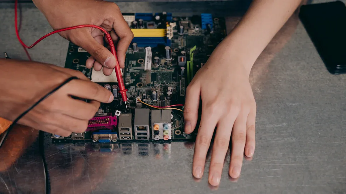
Proper hardware setup ensures the consistent performance of the W5500 module. Following best practices during installation can prevent issues with the Link/ACT LEDs.
-
Use High-Quality Components
Select reliable Ethernet cables, connectors, and power supplies. Poor-quality components often lead to signal degradation and connectivity problems. -
Ensure Correct Pin Connections
Verify that all pins are securely connected. Loose or floating pins can disrupt the module’s operation. For example, grounding the CS pin properly prevents interference with critical functions like IP address retrieval. -
Optimize PCB Layout
Maintain proper impedance control and use solid reference planes in the PCB design. These measures improve signal integrity, reducing the likelihood of LED malfunctions. -
Follow Manufacturer Guidelines
Adhere to the module’s documentation for jumper settings and voltage requirements. Incorrect configurations can lead to hardware failures.
By implementing these practices, users can minimize hardware-related issues and ensure the LEDs function as intended.
Regular Maintenance and Updates
Routine maintenance and timely updates play a crucial role in preventing future problems. Neglecting these tasks can lead to performance degradation over time.
-
Inspect Hardware Regularly
Check for loose connections, damaged cables, or worn-out components. Replace faulty parts immediately to avoid disruptions. -
Update Firmware Periodically
Install the latest firmware versions to benefit from bug fixes and performance improvements. Firmware updates often address known issues, including LED malfunctions. -
Monitor Performance Indicators
Evaluate the module’s performance using key metrics. For instance, operational efficiency and resource utilization improve significantly with preventive measures.Indicator
Description
Operational Efficiency
Enhanced diagnostic patterns and resource utilization through better setups.
Cost-Efficiency
Reduced unnecessary visits and improved cost-effectiveness.
-
Leverage Tele-EMS Practices
Integrating tele-EMS consultations has shown better outcomes in chronic disease management. This approach also enhances operational efficiency and reduces unnecessary interventions.
Tip: Schedule regular maintenance checks and keep a log of updates. This practice ensures the module operates smoothly and prevents recurring issues.
By combining proactive maintenance with hardware best practices, users can achieve sustained improvements in the W5500 module’s performance.
By following the outlined troubleshooting steps, users can effectively resolve the Link/ACT LEDs issue on the W5500 module. Checking hardware connections, verifying configurations, and updating firmware are essential actions to restore functionality.
Tip: Regularly inspect the module and update its firmware to prevent recurring problems.
Proper setup and routine maintenance ensure the module operates smoothly over time. Adopting best practices, such as using high-quality components and optimizing PCB layouts, further enhances performance and reliability. These measures help users maintain consistent connectivity and avoid future disruptions.

What should I do if the Link LED stays off after connecting the RJ45 cable?
Ensure the Ethernet cable is functional and securely connected. Verify that the LNK circuit on the module is closed. Check the power supply and confirm the module receives sufficient voltage. Testing with a known working setup can help isolate the issue.
Can mismatched voltage levels cause the LEDs to malfunction?
Yes, mismatched voltage levels can disrupt the module’s operation. Ensure the MEAS jumper is closed to tie VCC to the 5V input. Use a multimeter to confirm the voltage matches the module’s requirements.
How often should I update the W5500 firmware?
Update the firmware whenever a new version becomes available. Regular updates fix bugs, improve compatibility, and enhance performance. Always back up the current configuration before performing an update.
Why is grounding the CS pin important?
A floating CS pin can interfere with the module’s communication with the microcontroller. Proper grounding ensures stable operation and prevents issues like LED malfunctions or failed IP address retrieval.
What tools can I use to test the W5500 module?
Use a USB-to-serial adapter to connect the module to a computer. Upload a simple Ethernet test program, such as the Arduino Ethernet library, to verify connectivity. A multimeter can also help check voltage levels and pin connections.
Tip: Always use high-quality Ethernet cables and a stable power supply during testing to avoid false errors.
See Also
Simplified Networking Strategies for XILINX XC7K325T-2FFG676C
Integrating ATA5824C Effectively in Remote Control Applications
Three Effective Methods for MC9S12XET512VAG Integration
Uncovering LPQ252-CEF for Optimal Power Management Solutions
Guide to Seamless Sensor Integration with SN74LVC4245APW

