A digital potentiometer is an electronic component that offers digitally controlled variable resistance. It replaces traditional mechanical potentiometers. This high-precision digital variable resistor provides precise, automated adjustments. It also offers remote control capabilities, eliminates mechanical wear and noise, and allows for fine step resolution. These devices are indispensable in many applications, including automated volume control and LED brightness adjustment. In consumer electronics, where these potentiometers are crucial for such control, the market value reached 1,050 USD Million in 2024. They also find use in sensor calibration and programmable power supplies, with significant growth in industrial automation and aerospace & defense for precise control. This blog provides a clear, step-by-step tutorial on how to select, wire, and program these potentiometers with microcontrollers for precise control in your projects. If you want to buy digital potentiometer components, understanding these principles is key.
Key Takeaways
-
Digital potentiometers replace old mechanical knobs. They use digital signals to change resistance. This gives you precise control in your projects.
-
Choose the right digital potentiometer by checking its resistance, how many steps it has, and its communication type like SPI or I2C. Make sure your microcontroller, like Arduino, can talk to it.
-
Connecting a digital potentiometer to a microcontroller involves specific wiring. You send commands through code to set the resistance. This lets you control things like LED brightness.
-
Digital potentiometers are useful for many projects. You can use them for volume control, dimming lights, or even in robots. They offer reliable and automated control.
Digital Potentiometer Basics
How Digital Pots Work
A digital potentiometer functions as a variable resistor controlled by digital signals. Internally, it contains a resistor ladder integrated circuit. This ladder consists of many small, fixed resistors connected in series. Switches connect to each step on this resistor ladder. A digital-to-analog converter often manages the precise positioning. A “wiper” then connects to one of these points along the ladder. This connection determines the output resistance. Microcontrollers send digital commands to move this wiper. These commands typically use serial communication protocols. Common protocols include SPI (Serial Peripheral Interface) or I2C (Inter-Integrated Circuit). An up/down interface also exists for simpler control. These digital signals precisely control the wiper’s position, setting the resistance value.
Digital Potentiometer Specifications
Digital potentiometers offer significant advantages over traditional analog potentiometers. They provide superior reliability because they lack moving mechanical parts. This design also saves space on circuit boards. Digital versions offer a much wider range of resolution steps for finer control. They are also insensitive to harsh environmental conditions like vibration or dust. Engineers can choose between volatile and non-volatile types. Non-volatile digital potentiometers retain their last setting even after power loss. Furthermore, digital potentiometers boast significantly more writing cycles compared to mechanical parts. This makes them ideal for applications requiring frequent adjustments. The I2C interface is particularly popular for its simplicity in connecting multiple devices. This I2C communication allows for easy control from a microcontroller.
Selecting Your Digital Potentiometer and MCU
Choosing the right components ensures project success. This section guides you through selecting the appropriate digital potentiometer and microcontroller for your needs.
Choosing the Right Digital Potentiometer
Selecting a digital potentiometer involves matching its specifications to your project requirements. Consider the resistance range, the number of taps (which determines resolution), the communication interface, and the operating voltage. For example, a 10kΩ potentiometer with 256 taps offers finer control than a 100kΩ potentiometer with 64 taps. Common interfaces include SPI and I2C.
Here are some popular digital potentiometer series and their characteristics:
|
Model Series |
Potentiometers |
Resistance (KΩ) |
Interface |
Typical Applications |
|---|---|---|---|---|
|
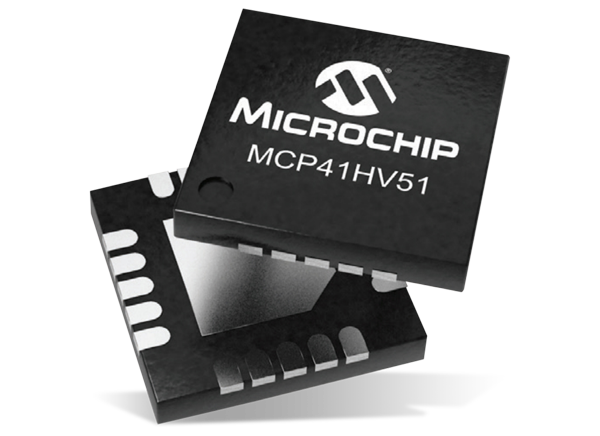
MCP41xxx |
1 |
10, 50, 100 |
SPI |
Rheostat mode, adjustable voltage divider |
|
MCP42xxx |
2 |
10, 50, 100 |
SPI |
Rheostat mode, adjustable voltage divider |
|
AD524X |
1 |
10, 50, 100 |
I2C |
Audio control, sensor calibration |
|
X9C10X |
1 |
10, 50, 100 |
Up/Down |
General purpose resistance control |
The MCP4131 is a single-channel SPI potentiometer, useful for simple resistance control. The AD5245 is an I2C potentiometer, often found in audio applications. The X9C10X series offers a simpler up/down interface for basic control. Match the potentiometer’s resistance to the circuit it will control. Ensure the number of taps provides enough resolution for your application.
Microcontroller Compatibility
Your microcontroller board must support the digital potentiometer’s communication interface. Common microcontroller options include Arduino, ESP32, and Raspberry Pi Pico. Each offers different capabilities for controlling a potentiometer.
Arduino boards, like the Uno or Nano, are excellent for beginners. They provide built-in libraries for both SPI and I2C communication. This makes them suitable for controlling many digital potentiometer models. For example, an Arduino can easily manage an I2C potentiometer for volume control.
The ESP32 microcontroller is a powerful option. It includes a rich peripheral set. This set specifically features SPI and I2C interfaces. This makes the ESP32 highly versatile for complex projects requiring precise control. You can use an ESP32 to control multiple I2C potentiometers simultaneously.
Raspberry Pi Pico also supports SPI and I2C. It offers a good balance of performance and cost. This makes it another strong choice for interfacing with various digital potentiometer types. An example project might use a Pico to adjust sensor gain with an SPI potentiometer.
Interfacing Digital Potentiometers with Microcontrollers: A Step-by-Step Guide
This section provides a practical guide for connecting and programming a digital potentiometer with a microcontroller. It uses an SPI digital potentiometer, such as the MCP4131, with an Arduino board as the primary example. This step-by-step guide helps users achieve precise control in their projects.
Materials Needed
To begin interfacing with microcontrollers, gather the necessary components. This example uses an Arduino Uno for its ease of use and widespread support.
-
Arduino Board: An Arduino Uno or a compatible board.
-
Digital Potentiometer: An MCP4131 (or similar SPI digital potentiometer like MCP41100).
-
Resistor: One 100 Ohm resistor.
-
LED: One standard LED.
-
Breadboard: For prototyping connections.
-
Jumper Wires: For making electrical connections.
The MCP41100 digital potentiometer communicates with the Arduino Board using the SPI protocol. This serial communication method allows the microcontroller to send commands to the potentiometer.
Wiring Diagram and Connections
Connecting the digital potentiometer to the Arduino requires careful attention to the SPI pins. The Arduino communicates with the MCP4131 via the SPI bus. Arduino pins D11 to D13 are configured for SPI communication. Pin D10 serves as a configurable Chip Select signal. Due to pin limitations on the MCP4131, incoming and outgoing SPI communication multiplexes through a single pin (pin 3). A 100 Ω resistor (R1) is recommended if a voltage difference exists between the Arduino and MCP4131, though it is sufficient for 5V operation. The output sets up as a voltage divider, nominally varying from 0 to 5V.
Here is a detailed connection table for the MCP4131 with an Arduino Uno:
|
Device |
SPI Function |
Arduino Uno Pin |
MCP4131 Pin |
|---|---|---|---|
|
Arduino Uno |
SS/CS |
10 |
N/A |
|
Arduino Uno |
MOSI |
11 |
SDI/SDO (Pin 3) |
|
Arduino Uno |
MISO |
12 |
SDI/SDO (Pin 3) |
|
Arduino Uno |
SCLK |
13 |
SCK (Pin 2) |
|
MCP4131 |
SDI/SDO |
N/A |
3 |
|
MCP4131 |
SCK |
N/A |
2 |
Additionally, connect the power and ground pins of the digital potentiometer:
|
Pin # |
Pin Name |
Description |
|---|---|---|
|
1 |
CS |
Chip Select (SS) for SPI interface; active low (0V selected, 5V not selected). |
|
2 |
SCLK |
Shared/Serial Clock for SPI. |
|
3 |
SDI/SDO |
Serial Data In and Out (MOSI and MISO). |
|
4 |
VSS |
Ground connection. |
|
5 |
PA0 |
One terminal of the potentiometer. |
|
6 |
P0W |
Wiper terminal of the potentiometer, connected to the output device. |
|
7 |
P0B |
Connected to ground. |
|
8 |
VDD |
Connected to the +5V terminal on the Arduino. |
Connect the LED to the wiper terminal (P0W) of the potentiometer and then to ground through a current-limiting resistor. This setup allows the potentiometer to control the LED’s brightness.
Arduino Code Walkthrough
Programming the Arduino to control the digital potentiometer involves sending specific commands over the SPI serial interface. This example uses the SPI.h library, which comes standard with the Arduino IDE. For more complex digital potentiometers, specialized libraries often simplify the programming process. For instance, the ‘arduino-mcp4xxx’ library specifically controls Microchip’s MCP4XXX range of SPI-controlled digital potentiometers, including the MCP4131. It supports various configurations and memory types. For digital potentiometers with simpler protocols, such as the AD5206, users can directly use the general Arduino SPI library without needing a device-specific library. This approach demonstrates the underlying mechanism of more complex SPI libraries. The ‘MCP4251’ library, authored by Kulbhushan Chand, also controls the MCP4251 digital potentiometer.
Here is a general structure for setting the wiper position of an SPI digital potentiometer:
-
Initialize SPI: Set up the SPI communication pins and mode.
-
Take the slave select pin LOW: This signals the chip to prepare for commands.
-
Send the memory address: Use SPI to send the address for the desired wiper or terminal connection. For example,
wiper0writeAddr = B00000000;for the MCP4251. -
Send the new value: Provide the new wiper position (e.g., 0-255 for MCP4251). This value directly controls the resistance.
-
Take the slave select pin HIGH: This executes the changes.
Here is a basic code example for setting the potentiometer’s wiper position:
#include <SPI.h>

const int CS_PIN = 10; // Chip Select pin for the digital potentiometer

void setup() {
  Serial.begin(9600);
  SPI.begin(); // Initialize SPI communication
  pinMode(CS_PIN, OUTPUT);
  digitalWrite(CS_PIN, HIGH); // Deselect the chip initially
}

void loop() {
  // Example: Set potentiometer to half resistance (127 out of 255 taps)
  setPotentiometerValue(127);
  delay(2000);

  // Example: Set potentiometer to full resistance (255 taps)
  setPotentiometerValue(255);
  delay(2000);

  // Example: Set potentiometer to minimum resistance (0 taps)
  setPotentiometerValue(0);
  delay(2000);
}

void setPotentiometerValue(byte value) {
  digitalWrite(CS_PIN, LOW); // Select the digital potentiometer
  SPI.transfer(0x00);        // Command byte for writing to Wiper 0 (MCP4131 example)
  SPI.transfer(value);       // Send the desired wiper value
  digitalWrite(CS_PIN, HIGH); // Deselect the digital potentiometer
  Serial.print("Potentiometer set to: ");
  Serial.println(value);
}
This example demonstrates how to send commands to control the potentiometer. You can modify the setPotentiometerValue function to accept different values or integrate it into more complex control logic.
Testing and Troubleshooting
After wiring and programming, testing the setup ensures proper functionality. Observe the LED brightness changing according to the code’s commands. If the system does not work as expected, troubleshooting becomes necessary.
Common issues encountered during digital potentiometer interfacing include:
-
Compatibility Issues: These arise when the specifications (pin assignments, voltage levels, communication protocols) of the digital potentiometer and microcontroller do not align. Review datasheets thoroughly. Ensure alignment of voltage levels and communication interface.
-
Programming Difficulties: Some digital potentiometers require specific programming or configuration commands. Follow manufacturer guidelines and refer to application notes. For example, some digital potentiometers might use an I2C interface instead of SPI, requiring different libraries and communication protocols.
-
Wiring Errors: Double-check all connections against the wiring diagram. Incorrect pin assignments for SPI (MOSI, MISO, SCLK, CS) or power/ground can prevent communication.
-
Noise and Signal Integrity Problems: These can occur due to impedance mismatches or improper grounding. Review the system design and implement shielding techniques if necessary. Ensure proper grounding for both the Arduino and the potentiometer.
By systematically checking these areas, users can resolve most issues and achieve reliable control with their digital potentiometer.
Advanced Digital Potentiometer Applications
This section explores more practical uses for digital potentiometers. It also covers alternative ways to connect them to microcontrollers.
I2C Digital Potentiometer Interfacing
Connecting an I2C digital potentiometer differs from an SPI version. I2C communication uses fewer wires. This makes it simpler for many projects.
Here are key differences in wiring between SPI and I2C digital potentiometers:
|
Feature |
SPI Digital Potentiometer |
I2C Digital Potentiometer |
|---|---|---|
|
Chip Select |
Requires a separate Chip Select for each device. |
All devices can connect on the same bus due to addressability. |
|
Data Lines |
Dedicated data input (MOSI) and output (MISO) lines. |
Data input pin can also function as a data output (bidirectional). |
|
Signal Drive |
Data lines are actively driven (high/low). |
Uses passive pull-ups, which may affect maximum speeds or loads. |
For I2C, you typically connect the microcontroller’s SDA (Serial Data) pin to the potentiometer’s SDA pin. You also connect the microcontroller’s SCL (Serial Clock) pin to the potentiometer’s SCL pin. Each I2C device has a unique address. This allows multiple I2C devices to share the same two wires.
Many I2C digital potentiometers exist. The Analog Devices AD5259 is one example. It offers 256 positions and an I2C interface. It supports programmable gain/offset control, programmable power supplies, and LED brightness adjustment.
Arduino users can find specific libraries for I2C control. The AD5144A Library supports a family of Analog Devices I2C potentiometers. These include the AD5144 (4 potentiometers, 256 steps) and AD5122A (2 potentiometers, 127 steps). This library simplifies I2C communication with these devices.
Practical Project Ideas
Digital potentiometers offer versatile control in many applications.
-
Volume & Audio Gain Control: Digital potentiometers can replace mechanical knobs in audio systems. They provide precise volume control. For professional audio, dedicated ICs like the PT2258 offer better performance. These ICs provide accurate 1dB steps and remote control. Digital potentiometers can still work well in hobby audio projects. They can mimic logarithmic audio tapers through software. This matches how humans hear sound.
-
LED Dimming & Lighting Control: You can use a digital potentiometer to adjust LED brightness. Digital potentiometers have low current capacity. They cannot directly drive LEDs. Instead, use the potentiometer as a reference voltage source. Then, connect its output to a buffer op-amp. The op-amp provides the necessary current to drive the LEDs. This setup allows precise control over lighting.
-
Motor Control & Robotics: Digital potentiometers help configure motor control systems. They can adjust motor driver thresholds or speed control loops. This allows for precise position and speed control of DC motors. Engineers can use them to tune robotic systems. This helps find optimal parameters for stable operation.
-
Industrial & Measurement Equipment: Industries use digital potentiometers for remote adjustment and automated control. They replace mechanical knobs in programmable power supplies. This allows electronic setting of output voltage or current. They also help calibrate sensors in industrial and medical systems. This provides precision control and automated calibration.
Digital potentiometers offer precise, automated, and reliable control in microcontroller projects. This guide demonstrated the ease of implementing these versatile components. Readers can now confidently incorporate them into their designs. They should explore the wide array of applications discussed and experiment to innovate electronic designs. Digital control holds transformative potential in modern embedded systems.
What is the main difference between a digital and a mechanical potentiometer?
A digital potentiometer uses electronic signals to adjust resistance. It has no moving parts. A mechanical potentiometer uses a physical knob. This knob moves a wiper across a resistive track. Digital versions offer precise, automated control and greater durability.
What communication protocols do digital potentiometers use?
Digital potentiometers commonly use serial communication protocols. These include SPI (Serial Peripheral Interface) and I2C (Inter-Integrated Circuit). Some simpler models use an up/down interface. Microcontrollers send commands through these protocols.
Can digital potentiometers handle high power?
Generally, digital potentiometers handle low power. They are not suitable for directly controlling high-current loads. Engineers often use them to set reference voltages or control signals. These signals then drive power stages.
Are digital potentiometers volatile or non-volatile?
Digital potentiometers come in both volatile and non-volatile types. Volatile types lose their settings when power is off. Non-volatile types save their last setting. They restore this setting when power returns.
See Also
SPC56 Microcontrollers: Mastering Automotive Powertrain Applications and Core Engine Control
STM32F103C8T6 MCU: Integrating Bluetooth Control for Advanced Robotic Systems
NXP Microcontrollers: Powering Automotive Electronics with Core Chip Analysis and Applications
MC9S12XD256 Microcontrollers: Essential Programming Techniques for Embedded System Development