Efficient gate driving is crucial in power electronics, impacting switching speed and overall energy efficiency. The Discrete Semiconductor Products 2N7002 for power MOSFET gate drivers offers a versatile, low-cost, and efficient solution. This component enhances driver circuits. A reliable semiconductor distributor makes the 2N7002 MOSFET widely available. This Discrete Semiconductor Products 2N7002 for power MOSFET gate drivers improves performance through current boosting, level shifting, and protection. These methods lead to faster switching, better efficiency, and increased robustness in various power applications.
Key Takeaways
-
The 2N7002 MOSFET helps power MOSFETs switch faster. It boosts the current to the gate. This makes power devices work better and use less energy.
-
The 2N7002 can change low-voltage signals to high-voltage signals. This helps control high-side MOSFETs. It lets small computer chips control bigger power parts.
-
The 2N7002 protects other parts in the circuit. It acts like a shield against sudden power spikes. This makes the whole power system more reliable and last longer.
-
Using the 2N7002 improves how power electronics work. It makes them more efficient and stable. This helps meet safety rules and makes devices work well together.
1. Boosting Power MOSFET Gate Drivers with Discrete Semiconductor Products 2N7002
The Role of Gate Current in Switching Speed
Power MOSFETs operate as switches. They turn on and off quickly. The speed of this switching depends heavily on the gate current. A MOSFET’s gate acts like a capacitor. To turn the MOSFET on or off, this gate capacitance must charge or discharge. The time it takes to do this directly relates to the gate current. Engineers use the formula t = Q / I. Here, ‘t’ represents time, ‘Q’ is the total gate charge, and ‘I’ is the gate current. For example, a MOSFET with a total gate charge (Qg) of 354nC needs a gate current of 1.2A to switch fully on in about 295ns. This calculation shows that a higher current (I) for a given charge (Q) results in a shorter switching time (t). This increases the switching speed. Purpose-built integrated gate drivers can source high currents, sometimes up to 10A. This charges the MOSFET gate very quickly. Fast charging minimizes power losses and increases switching speed. Logic-level MOSFETs generally have a lower maximum switching speed compared to standard MOSFETs. This is due to their higher gate charge.
2N7002 as a Current Buffer/Amplifier
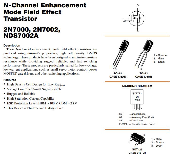
The discrete semiconductor products 2N7002 for power MOSFET gate drivers serve as an excellent current buffer or amplifier. This small, efficient 2N7002 MOSFET has a low gate charge. This allows it to be driven with less power. The 2N7002 is an n-channel enhancement mode device. It uses DMOS technology. This design gives it a low on-state resistance and high density cell design for low RDS(on). These features contribute to its efficiency. The 2N7002 is also known for its ruggedness and reliability. It offers fast switching performance. It functions as a voltage-controlled small signal switch. It also has a high saturation current. These characteristics make it suitable for low-voltage applications and low-current tasks, such as gate driving. The 2N7002 includes ESD protection, with HBM > 100 V and CDM > 2 kV. It is also Pb-Free and Halogen Free.
The 2N7002 has a typical gate-source threshold voltage (Vgs(th)) between 2.1V and 3V. A 3.3V gate drive signal is marginal for reliable operation. However, a 5V PWM signal is suitable for gate driving up to around 200kHz. This makes the 2N7002 MOSFET a practical choice for many digital control systems.
Push-Pull Configuration for Enhanced Current
Engineers often use the 2N7002 in a push-pull configuration. This setup uses two 2N7002 devices. One 2N7002 sources current to charge the main MOSFET gate. The other 2N7002 sinks current to discharge it. This configuration provides a strong current drive in both directions. The 2N7002 has a maximum continuous drain current (ID) of 300 mA. It can reliably deliver a continuous drain current of up to 200 mA. It can also accommodate maximum current spikes of up to 1 A. This current rating makes it suitable for signal switching applications. However, it is not recommended for directly driving motors or high-power LEDs due to this current limitation. Adhering to these operational constraints is crucial. It prevents potential damage to the component. Exceeding these current limits will damage the MOSFET. Despite its low drain current capability compared to larger power devices, the 2N7002 provides sufficient current for effective gate driving.
Benefits: Faster Switching, Reduced Losses
Using the discrete semiconductor products 2N7002 for power MOSFET gate drivers offers clear benefits. The enhanced current delivery from the 2N7002 allows the main power MOSFET to switch faster. Faster switching reduces the time the MOSFET spends in its transition state. This minimizes switching losses. Reduced losses lead to higher overall system efficiency. This also means less heat generation. The 2N7002 improves the dynamic performance of the entire power stage.
2. Level Shifting for High-Side Driving with 2N7002 MOSFET
High-Side Driving Challenges
High-side driving presents unique difficulties in power electronics. Driving the high-side MOSFET is more complex than driving the low-side. Its source potential is not fixed. It fluctuates with the output voltage. A significant challenge involves providing a gate voltage. This voltage must be higher than the high-side MOSFET’s source potential. Bootstrap circuitry is commonly used for voltage supply. However, bootstrap circuits introduce their own difficulties. These include proper sizing and charging of the bootstrap capacitor.
Challenges in high-side gate driving in half-bridge converters include issues with bootstrap biasing techniques. The impact of bootstrap diode forward and reverse current on gate driver performance is also a factor. Engineers must consider the effects of bootstrap capacitor value. The influence of switching frequency also plays a role. Different power supply topologies can present unique challenges to the gate driver IC and its bias supply.
Simple Level Shifting Solutions
The 2N7002 MOSFET offers a straightforward solution for level shifting. It bridges the gap between a low-voltage control signal and a high-voltage gate drive. This is essential for high-side switching. The 2N7002 is an n-channel enhancement mode field effect transistor. It can translate a ground-referenced control signal to a floating high-side voltage. This allows a low-voltage microcontroller to control a high-voltage power MOSFET.
Basic High-Side Driver Circuit
A basic high-side driver circuit using the 2N7002 MOSFET typically involves a few components. The 2N7002 acts as a switch. It pulls down a resistor connected to the high-side supply. This action creates a voltage drop. This voltage drop then drives the gate of the main power MOSFET. The 2N7002’s low gate charge and fast switching speed make it effective in this role.
Transistors like 2N7002 are rather bulky affairs (~30pF Cout) and go slowly as claimed, with large pullups (10k+). They’re quite fast if you don’t happen to mind drawing 10s or 100s of mA.
This highlights that while the 2N7002 is fast, its speed depends on the surrounding circuit components, especially pull-up resistors. The 2N7002 has specific voltage and current limitations.
|
Feature |
Description |
|---|---|
|
Continuous Drain Current (ID) |
200mA |
|
Drain-Source Voltage (VDS) |
60V |
|
Gate Threshold Voltage (VGS-th) (Min) |
1V |
|
Gate Threshold Voltage (VGS-th) (Max) |
3V |
The 2N7002 has a moderately low drain current. It reliably delivers up to 200mA continuously. It can accommodate maximum current spikes of up to 1A. To prevent potential damage, adhering to these operational constraints is crucial in practical applications. The Drain-Source Voltage (VDS) is 60V. The gate threshold voltage (VGS-th) ranges from 1V to 3V. A typical value is approximately 2.1V. This makes it suitable for 3.3V circuits.
Compatibility with Control Voltages
The 2N7002’s gate threshold voltage (Vgs(th)) is important for compatibility with control signals.
|
Feature |
Description |
|---|---|
|
Gate Threshold Voltage (VGS-th) (Min) |
1V |
|
Gate Threshold Voltage (VGS-th) (Max) |
3V |
|
On-State Resistance |
< 5Ω |
|
Continuous Drain Current (ID) |
200mA |
|
Drain-Source Voltage (VDS) |
60V |
|
Turn ON Time |
15ns |
|
Turn OFF Time |
8ns |
The 2N7002, an n-channel Logic Level MOSFET, is primarily suitable for circuits operating at 3.3V. This is due to its low on-state resistance. Its gate-source threshold voltage is approximately 2.1V. These features contribute to enhanced energy efficiency and optimized switching performance in such applications.
Using a 3.3V source to control the 2N7002 raises concerns. The RDSon is typically specified only for 5V, not 3.3V. The gate threshold (max 2.1V) indicates the voltage at which the transistor begins to switch on. It does not indicate when it is fully on. While 3V might be sufficient for typical Vgs threshold values (around 1.6V), the worst-case scenario requires approximately 3.5V. This ensures adequate switching when the Vgs threshold is 2.1V. This is especially critical considering potential voltage tolerances. A 3.3V signal could drop to 3.2V. For 5V control signals, compatibility is generally better. RDSon is specified for 5V. Also, 5V is well above the maximum Vgs(th) of 3V. This ensures the transistor is fully switched on.
3. Protecting Gate Driver ICs and Enhancing Robustness
Gate Driver IC Vulnerabilities
Gate driver integrated circuits (ICs) are crucial components in power electronics. They control the switching of power MOSFETs. However, these ICs are often vulnerable to various electrical stresses. High voltage spikes can occur on the gate or source pins. These spikes can exceed the IC’s maximum ratings. Current surges, especially during fault conditions, also pose a significant threat. Electrostatic discharge (ESD) events can damage sensitive internal circuitry. Noise from the switching power stage can couple back into the control signals. This noise can cause erratic behavior or even permanent damage. Without proper protection, these vulnerabilities reduce the lifespan and reliability of the entire power conversion system.
2N7002 for Isolation and Protection
The 2N7002 offers an effective solution for isolating and protecting gate driver ICs. Engineers can place the 2N7002 as a buffer stage between the driver IC and the main power MOSFET. This small, rugged transistor acts as a barrier. It absorbs transient voltages and currents. This prevents them from reaching the more sensitive driver IC. The 2N7002 features robust ESD protection. This protection level helps shield the driver IC from external static discharges. Its fast switching capability ensures that it does not significantly delay the gate drive signal. This isolation strategy enhances the overall robustness of the gate drive circuit. It safeguards the driver IC from the harsh electrical environment of the power stage.
Active Gate Clamping and Pre-Driver Stages
The 2N7002 also plays a vital role in active gate clamping and pre-driver stages. Active gate clamping circuits prevent the gate-source voltage of the main power MOSFET from exceeding a safe limit. This is especially important during turn-off transients or fault conditions. A 2N7002 can be configured to shunt excess gate voltage to ground or a clamping voltage. This protects the main MOSFET from overvoltage stress.
Active gate clamping helps prevent gate oxide breakdown, a common failure mode for power MOSFETs.
Furthermore, engineers use the 2N7002 in pre-driver stages. These stages condition the control signal before it reaches the main gate driver. A pre-driver stage can sharpen the rising and falling edges of the gate signal. It can also provide additional current boosting. This ensures the main driver IC operates within its optimal parameters. The 2N7002’s voltage-controlled small signal switch characteristics make it ideal for these precise control functions.
Improved Reliability and EMI Performance
Integrating the 2N7002 into gate drive circuits significantly improves system reliability. By protecting the driver ICs from electrical stresses, the 2N7002 extends their operational life. This reduces the likelihood of premature failures. Enhanced gate control, achieved through current boosting and active clamping, leads to more predictable and stable switching. This stability minimizes voltage and current overshoots. These overshoots are common sources of electromagnetic interference (EMI). Reduced EMI is crucial for meeting regulatory standards and ensuring compatibility with other electronic systems. The 2N7002 contributes to a more robust, efficient, and electromagnetically compliant power electronics design.
Key Integration Considerations for the 2N7002
Selecting Gate Resistors
Choosing the right gate resistor is important for 2N7002 circuits. This resistor controls the current flowing into the gate of the main power MOSFET. A smaller resistor allows more current. This makes the MOSFET switch faster. However, a very small resistor can cause ringing. Ringing is unwanted oscillations in the circuit. It can lead to electromagnetic interference (EMI). A larger resistor limits current. This slows down switching. Slower switching increases power losses. Engineers must find a balance. They select a resistor value that provides fast switching without excessive ringing or EMI. This ensures stable and efficient operation.
Thermal Management
Proper thermal management is crucial for the 2N7002. Like all electronic components, the 2N7002 generates heat during operation. This heat comes from power dissipation. Excessive heat can damage the device. It can also reduce its lifespan. The 2N7002 has a power dissipation cap of 200mW. Adhering to this specification is crucial for preserving circuit integrity and prolonging performance reliability in practical applications, including gate drivers. Engineers must ensure the 2N7002 operates within its temperature limits. They might use heat sinks or ensure good airflow. This prevents overheating. It maintains the device’s performance and reliability.
Optimal Layout Practices
Circuit board layout significantly impacts the performance of 2N7002 driver circuits. Poor layout can introduce parasitic inductance and capacitance. These unwanted elements degrade switching performance. They can also cause noise. Good layout practices minimize these issues.
-
Shorten Trace Lengths: Keep traces as short as possible. This is especially true for high-speed signals and power delivery. Use direct routes with minimal bends. Avoid meandering traces to reduce inductance.
-
Minimize Via Usage: Each via adds parasitic inductance and capacitance. Route high-speed signals on the same layer when feasible. If vias are necessary, keep them short. Consider blind or buried vias for critical signals.
-
Ensure Proper Grounding: Utilize a solid ground plane directly beneath signal traces. This provides a low-inductance return path. Maintain continuous ground connections across layers. Avoid splitting the ground plane.
-
Separate Power and Signal Traces: Keep power and signal traces distinct. This reduces coupling and noise. Route power and ground on dedicated layers. Use ground shielding for sensitive signals to minimize crosstalk.
-
Minimize Loop Areas: Reduce inductance by minimizing the area of current loops. Use short, wide traces for power and ground. Route signal and return paths close to each other. For example, route them over a solid ground plane.
The discrete semiconductor products 2N7002 for power mosfet gate drivers offers significant value. This versatile, cost-effective component boosts gate driver performance. It provides enhanced current delivery, effective level shifting, and robust protection. The 2N7002 optimizes power electronics designs. This leads to improved energy efficiency, reliability, and switching speed for any power mosfet. Designers should implement these techniques to enhance their power electronics projects. The discrete semiconductor products 2N7002 for power mosfet gate drivers truly elevates system capabilities.
What is the 2N7002’s main role in gate drivers?
The 2N7002 boosts current for power MOSFET gates. It acts as a buffer or amplifier. This helps the main MOSFET switch faster. Faster switching reduces power losses and improves efficiency in power electronics.
Can the 2N7002 handle high currents?
The 2N7002 has a continuous drain current of 200mA. It can handle current spikes up to 1A. This makes it suitable for gate driving signals. It is not for directly driving high-power loads like motors or large LEDs.
How does the 2N7002 help with level shifting?
The 2N7002 translates low-voltage control signals to higher voltages. This allows microcontrollers to drive high-side MOSFETs. It functions as a voltage-controlled small signal switch for this purpose.
The 2N7002’s N-channel enhancement mode design makes it effective for translating logic levels.
How does the 2N7002 protect gate driver ICs?
The 2N7002 acts as a buffer. It isolates the driver IC from voltage spikes and current surges. It also features robust ESD protection. This shields the sensitive driver IC from harsh electrical conditions in the power stage.
What control voltage is best for the 2N7002?
A 5V PWM signal works well for driving the 2N7002. Its gate threshold voltage is typically 2.1V. While 3.3V can work, 5V ensures the transistor fully switches on for optimal performance and reliability.
See Also
IRF820 N-Channel MOSFET: Powering Management, Converters, and Motor Control
NXP Microcontrollers: Automotive Electronics’ Core Power, Analysis, and Applications
EP2C50F484I8N FPGA: Unlocking High-Performance Embedded System Design Possibilities
Mastering Automotive Powertrains: SPC56 Microcontroller Applications for Engine Core
AD620AN Instrumentation Amplifier: Analysis and Practice in TV Power