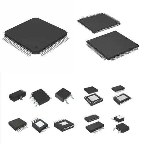
The dsPIC Microcontroller IC DSPIC33EP256MU806-E/PT works well for fast PWM tasks. Its detailed PWM modules provide accurate control, making it perfect for motor systems. Engineers utilize its quick processing and built-in tools to manage challenging motor tasks with ease. The DSPIC33EP256MU806-E/PT executes advanced motor control methods for seamless operation in robots, factories, and home appliances.
This robust microcontroller enhances real-time control and improves system reliability.
Key Takeaways
-
The dsPIC33EP256MU806-E/PT microcontroller is great for motor control. It uses high-resolution PWM modules to manage speed and power accurately.
-
Engineers can use built-in tools like ADC and QEI to check motor performance in real-time. This helps make the system more reliable.
-
Fast processing at 60 MIPS allows advanced methods like Field-Oriented Control (FOC). This makes motors work better and more efficiently.
-
Setting up hardware correctly, like pins and power supply, is very important for good motor control.
-
MPLAB X IDE and MCC make software setup easier. They help configure PWM modules and add motor control programs.
Features of dsPIC Microcontroller IC DSPIC33EP256MU806-E/PT
High-Resolution PWM Modules
The dsPIC Microcontroller IC DSPIC33EP256MU806-E/PT has special PWM modules. These modules help control motor speed and power precisely. They work with a very fine resolution of 8.32 nanoseconds. This allows smooth and accurate motor operation. It can support up to seven PWM generators. This makes it great for systems needing many control channels.
These high-resolution PWM modules are key for robots and factories. Precision improves how well these systems work.
|
Feature |
Specification |
|---|---|
|
PWM Resolution |
8.32 ns |
|
PWM Generators |
Up to seven |
|
Motor Control Peripherals |
Advanced Motor Control Peripherals (PWM, QEI) |
Common Companion Chips
Used alongside dsPIC33EP256MU806 for enhanced system design:
-
MCP8025 – 3-phase motor driver + LIN transceiver
-
MIC4605 – 85V half-bridge MOSFET driver
-
ATA6563 – High-speed CAN transceiver
-
25LC256 – External SPI EEPROM if Flash is insufficient
-
ATECC608A – Security authentication co-processor
Integrated Peripherals for Motor Control
The DSPIC33EP256MU806-E/PT has built-in tools made for motor control. These include PWM modules, Quadrature Encoder Interface (QEI), and ADC channels. It has two ADC modules with up to 32 channels. These help monitor motor details like current and voltage in real time.
It also has communication tools like USB OTG, CAN, and LIN. These make it easy to connect with other devices. This is useful for things like factory machines and HVAC systems.
|
Feature |
Specification |
|---|---|
|
ADC Modules |
Two independent ADC modules |
|
Analog Channels |
Up to 32 channels |
|
Communication Interfaces |
USB 2.0 OTG, ECAN™ modules |
Fast Processing and DSP Capabilities
The DSPIC33EP256MU806-E/PT is very fast and good at math tasks. It runs at 60 MIPS, making it handle motor control easily. It can do advanced tasks like Field-Oriented Control (FOC). Its DSP core helps with math for filtering and reducing noise.
It works in tough conditions, from 3.0V to 3.6V and -40ºC to +125ºC. This makes it great for sensorless motors and digital power systems.
-
Speed: 60 MIPS
-
Operating Conditions: 3.0V to 3.6V, -40ºC to +125ºC
The DSP features make this microcontroller a top pick for engineers. It’s perfect for fast motor control and signal tasks.
Hardware Setup for High-Speed PWM Applications

Pin Setup for Motor Control
Setting up pins correctly is important for motor control. The dsPIC33EP256MU806-E/PT has flexible pins for motor drivers, sensors, and communication. Start by finding the pins needed for PWM, QEI, and ADC.
The microcontroller has up to seven PWM outputs. These connect to motor driver inputs to control speed and power. QEI pins track motor position and direction. Hooking them to an encoder gives accurate feedback for control. ADC pins connect to sensors that check current and voltage. This helps monitor and adjust in real time.
Tip: Add pull-up or pull-down resistors to unused pins. This stops floating signals and keeps the system stable.
Power Supply and Reducing Noise
A good power supply keeps the microcontroller running smoothly. Design it to give 3.0V to 3.6V, as required. Use low-noise regulators with filters to reduce voltage ripple and EMI.
Place decoupling capacitors close to the power pins. These help cut noise and keep voltage steady during quick changes. Use shielded cables and proper grounding to lower noise in high-EMI areas.
Note: Keep power lines away from high-frequency signal paths to avoid interference.
Software Configuration and Programming
Setting Up PWM Modules in MPLAB X IDE
Setting up PWM modules in MPLAB X IDE is simple. The MCC tool helps make the process easier. The dsPIC Microcontroller IC DSPIC33EP256MU806-E/PT offers flexible PWM settings. These can be adjusted to fit motor control needs.
-
Open MPLAB X IDE: Start a new project. Choose the dsPIC Microcontroller IC DSPIC33EP256MU806-E/PT as the device.
-
Turn On PWM Modules: Use MCC to enable PWM modules. Assign pins for PWM outputs.
-
Adjust PWM Settings: Set frequency, duty cycle, and resolution. Match the frequency to the motor’s needs.
-
Create Code: Click “Generate Code” in MCC. This makes the setup code for PWM modules.
Tip: MCC’s visual tools help check PWM settings. This saves time and avoids mistakes.
Here’s an example of the generated code for setting up a PWM module:
void PWM_Initialize(void) {
    // Set PWM frequency and duty cycle
    PTPER = 1999; // 20 kHz period
    PDC1 = 1000;  // 50% duty cycle
    PTCONbits.PTEN = 1; // Enable PWM
}
Using Motor Control Algorithms
The dsPIC33EP256MU806-E/PT is great for advanced motor control. Its DSP core and PWM modules support methods like FOC and sensorless control.
-
Field-Oriented Control (FOC): This method makes motors more efficient. It controls the motor’s magnetic field. The DSP core handles the math needed for FOC.
-
Sensorless Control: ADC channels collect real-time data. This data estimates motor speed and position. No physical sensors are needed, lowering costs.
Note: Always test algorithms in a safe environment before using them in real systems.
Here’s an example of a basic motor control loop:
void MotorControl_Loop(void) {
    // Get current and voltage from ADC
    int current = ADC_ReadChannel(0);
    int voltage = ADC_ReadChannel(1);

    // Calculate speed and adjust PWM duty cycle
    int speed = CalculateSpeed(current, voltage);
    PDC1 = speed * 10; // Change duty cycle based on speed
}
Debugging and Improving Performance
Debugging and improving performance are important for motor control. The dsPIC33EP256MU806-E/PT has tools to help.
-
Use MPLAB X IDE Debugger: Step through the code and watch variables. Breakpoints help find problems in the motor control loop.
-
Check ADC and PWM Signals: Use an oscilloscope to view ADC and PWM signals. Make sure they are steady and correct.
-
Speed Up Code: Use DSP instructions for faster math. Inline assembly can help in critical parts.
Tip: Update firmware often to fix bugs and improve performance.
By following these steps, the dsPIC33EP256MU806-E/PT can perform well in motor control tasks.
Practical Uses of dsPIC33EP256MU806-E/PT
Example: Controlling DC Motors with PWM
The dsPIC33EP256MU806-E/PT is great for controlling DC motors. Engineers use it to adjust motor speed and power accurately. Its high-resolution PWM makes smooth changes easy. This is useful for things like conveyor belts, fans, and pumps.
To control a DC motor, it sends PWM signals to the motor driver. These signals change the motor’s speed by adjusting the duty cycle. A higher duty cycle makes the motor go faster. A lower duty cycle slows it down. The ADC modules check current and voltage to keep the motor safe.
Tip: Add sensors for feedback to make a closed-loop system. This improves control and stability.
Here’s an example of a simple PWM setup for a DC motor:
void DC_MotorControl(void) {
    // Set PWM frequency and duty cycle
    PTPER = 1999; // 20 kHz period
    PDC1 = 1500;  // 75% duty cycle
    PTCONbits.PTEN = 1; // Enable PWM
}
Example: Advanced Brushless Motor Control
Brushless motors, like BLDC and PMSM, need special control methods. The dsPIC33EP256MU806-E/PT supports techniques like trapezoidal control and FOC. These methods make motors efficient and quiet. They are used in robots, drones, and HVAC systems.
In trapezoidal control, the microcontroller switches motor phases using rotor position. The QEI module reads encoder data to find the rotor’s position. For FOC, the DSP core does math to control the motor’s magnetic field. This gives smooth movement and precise torque control.
Note: Sensorless control removes the need for physical sensors. ADC modules estimate rotor position using back-EMF signals, saving costs.
Here’s an example of a basic FOC setup:
void FOC_Control(void) {
    // Read current and voltage
    int current = ADC_ReadChannel(0);
    int voltage = ADC_ReadChannel(1);

    // Perform FOC calculations
    int torque = CalculateTorque(current, voltage);
    PDC1 = torque * 10; // Adjust PWM duty cycle
}
These examples show how flexible the dsPIC33EP256MU806-E/PT is for motor control. Its advanced tools allow accurate and efficient control, making it a top choice for engineers.
The dsPIC Microcontroller IC DSPIC33EP256MU806-E/PT is great for fast PWM tasks. It has advanced tools like high-resolution PWM and DSP features. These help motors run smoothly and efficiently. Setting up the hardware and software correctly is very important. Engineers can use its built-in tools to create smart control methods. Learning its features helps improve performance and handle modern motor control needs.
This microcontroller helps engineers build strong and efficient motor systems.
Why is the dsPIC33EP256MU806-E/PT good for motor control?
The dsPIC33EP256MU806-E/PT has high-resolution PWM modules. It processes fast at 60 MIPS and includes ADCs and QEI. These features allow accurate motor control and real-time feedback. It also supports advanced methods like Field-Oriented Control (FOC). Its strong design works well in factories and home devices.
Can the dsPIC33EP256MU806-E/PT work without sensors?
Yes, it can handle sensorless motor control. The ADC modules gather data like current and voltage. This data helps estimate motor speed and position. No physical sensors are needed, saving money and making designs simpler. It still keeps control accurate.
How does this microcontroller make motors more efficient?
It improves motor efficiency with advanced control methods like FOC. The DSP core does math to optimize torque and save energy. High-resolution PWM modules ensure smooth motor operation. ADCs give real-time feedback for precise adjustments.
What tools can program the dsPIC33EP256MU806-E/PT?
MPLAB X IDE and MPLAB Code Configurator (MCC) are used. MCC makes setup easier with a visual interface for PWM and ADC. These tools help developers save time when creating motor control systems.
Can the dsPIC33EP256MU806-E/PT work in tough conditions?
Yes, it works well in harsh environments. It operates between -40°C and +125°C. It also supports voltages from 3.0V to 3.6V. This makes it great for robots, industrial machines, and HVAC systems.
See Also
Understanding MC9S12DJ256MFUE Specs for Automotive Use
SPC56 Microcontrollers: Simplified Solutions for Engine Control
IRF820 N-Channel MOSFET for Power Management and Control
Using STM32F103C8T6 Microcontrollers for Bluetooth Robot Control
Enhancing Automotive Performance with NXP MC9S12 Microcontrollers

