The ICM-20948 sensor plays a crucial role in boosting project capabilities. This tiny powerhouse combines a gyroscope, accelerometer, and magnetometer, making it a versatile tool across various fields. From wearable devices to drones, its applications are vast and impactful. Mastering the integration of this sensor can lead to successful project outcomes. Whether in gaming, healthcare, or industrial IoT, understanding how to harness its full potential is key. Dive into the world of motion tracking and see how the ICM-20948 can transform your projects.
More Sensor in warehouse
ICM-20602, TDK InvenSense
ICM-20649,TDK InvenSense
BMP384,Bosch Sensortec,Pressure Sensor
BMP390, Bosch Sensortec,Pressure Sensor
LIS3MDLTR, ST,Magnetoresistive Sensor
TXS0108ERGYR,TI,Translators
Key Takeaways
-
Gather essential resources, including the ICM-20948 sensor, a compatible microcontroller, and necessary software tools, to ensure a smooth project start.
-
Set up a well-organized workspace with good lighting and essential tools to enhance your project efficiency and success.
-
Understand the ICM-20948’s key features, including its 9-axis motion tracking capabilities, to fully leverage its potential in your applications.
-
Follow a step-by-step connection guide for both Arduino and Raspberry Pi to seamlessly integrate the ICM-20948 into your projects.
-
Install the necessary libraries for your programming environment to simplify communication with the ICM-20948 and streamline your coding process.
-
Calibrate the sensor properly and reduce noise interference to ensure accurate data readings and optimal performance.
-
Explore advanced integration options with other sensors, such as GPS or environmental sensors, to expand the functionality of your projects.
Getting Started with ICM-20948
Embarking on a journey with the ICM-20948 sensor can be both exciting and rewarding. This section will guide you through the essential resources and initial setup to ensure a smooth start.
Necessary Resources
Before diving into the world of motion tracking, gather the necessary resources. Having the right tools at your disposal will make the process much more manageable.
Required Hardware Components
To get started, you’ll need a few key hardware components:
-
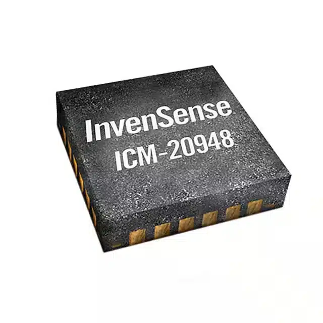
ICM-20948 Sensor: The heart of your project, this sensor combines a gyroscope, accelerometer, and magnetometer.
-
Microcontroller: Choose one that supports I2C or SPI communication, such as an Arduino or Raspberry Pi.
-
Connecting Cables: Ensure you have the appropriate cables for connecting the sensor to your microcontroller.
-
Breadboard: Useful for prototyping and testing connections without soldering.
Recommended Software Tools
Software tools play a crucial role in bringing your project to life. Here are some recommendations:
-
Arduino IDE: A popular choice for programming microcontrollers, especially if you’re using an Arduino board.
-
Python: If you’re working with a Raspberry Pi, Python offers a versatile platform for coding.
-
Sensor Libraries: Libraries like those from Adafruit or SparkFun simplify the integration of the ICM-20948 into your projects.
Initial Setup
With your resources in hand, it’s time to set up your workspace and prepare the sensor for action.
Unboxing and Inspecting the Sensor
When you first unbox the ICM-20948, take a moment to inspect it. Check for any visible damage or missing components. Familiarize yourself with its pin configuration and ensure you have all the necessary parts.
Preparing Your Workspace
A well-organized workspace can make a significant difference in your project’s success. Here’s how to prepare:
-
Clear Space: Ensure you have a clean, clutter-free area to work in.
-
Lighting: Good lighting helps you see small components and connections clearly.
-
Tools: Keep essential tools like screwdrivers, pliers, and a multimeter within reach.
By following these steps, you’ll be well on your way to integrating the ICM-20948 into your projects. With the right resources and a prepared workspace, you’re set for success.
Hardware Overview of ICM-20948
Understanding the hardware of the ICM-20948 is crucial for anyone looking to harness its full potential. This section will delve into the sensor’s key features, specifications, and how it connects with various boards.
Understanding the ICM-20948 Sensor
The ICM-20948 is a powerhouse in a compact package. It combines multiple sensors to provide comprehensive motion tracking capabilities.
Key Features and Specifications
The ICM-20948 is a 9-axis motion-tracking device, often referred to as a 9DOF IMU. It integrates:
-
3-Axis Gyroscope: Offers four selectable ranges for precise angular velocity measurements.
-
3-Axis Accelerometer: Also provides four selectable ranges, perfect for detecting linear motion.
-
3-Axis Magnetometer: Features a full-scale range (FSR) up to ±4900µT, ideal for orientation sensing.
This sensor includes a Digital Motion Processor (DMP) that offloads complex motion sensing algorithms from the main processor, enhancing performance and efficiency. Its low power consumption makes it suitable for applications in smartphones, tablets, and wearable devices.
Pin Configuration and Functions
The ICM-20948 features a straightforward pin configuration, making it easy to integrate into projects. Key pins include:
-
Power Supply Pins: Connect to the appropriate voltage source.
-
I2C/SPI Communication Pins: Enable data transfer between the sensor and microcontroller.
-
Interrupt Pin: Used for signaling events like data ready or motion detection.
Refer to the sensor’s datasheet for detailed pin functions and configurations.
Compatible Boards and Connections
Choosing the right microcontroller and understanding the connection process is vital for successful integration.
Supported Microcontrollers
The ICM-20948 is compatible with a variety of microcontrollers, including:
-
Arduino: Popular for its ease of use and extensive library support.
-
Raspberry Pi: Offers flexibility with Python programming.
-
ESP32: Known for its wireless capabilities and versatility.
These boards support I2C or SPI communication, essential for interfacing with the sensor.
Connection Diagrams
Connecting the ICM-20948 to your chosen microcontroller involves following specific diagrams. Here’s a basic outline:
-
Power Connections: Ensure the sensor receives the correct voltage.
-
Communication Lines: Connect the I2C or SPI pins to the corresponding pins on the microcontroller.
-
Interrupt Line: Optionally connect for advanced features like motion detection.
These diagrams are often included in the sensor’s documentation or can be found in community forums and GitHub repositories.
By understanding the hardware intricacies of the ICM-20948, users can effectively integrate this powerful 9DOF IMU into their projects, unlocking a world of motion tracking possibilities.
ICM-20948 Hookup Guide
Connecting the ICM-20948 sensor to your microcontroller is a crucial step in bringing your project to life. This hookup guide will walk you through the process, ensuring a seamless integration with both Arduino and Raspberry Pi platforms.
Step-by-Step Connection Guide
Connecting to an Arduino
-
Gather Your Components: Start by collecting the ICM-20948 sensor, an Arduino board, and some jumper wires.
-
Power Connections: Connect the VCC pin of the sensor to the 3.3V pin on the Arduino. Ground the sensor by connecting its GND pin to the Arduino’s GND.
-
I2C Communication: Use jumper wires to connect the SDA (data line) and SCL (clock line) pins of the sensor to the corresponding SDA and SCL pins on the Arduino.
-
Verify Connections: Double-check all connections to ensure they are secure and correct.
Connecting to a Raspberry Pi
-
Prepare Your Setup: Gather the ICM-20948 sensor, a Raspberry Pi, and the necessary connecting cables.
-
Power the Sensor: Connect the sensor’s VCC pin to the 3.3V pin on the Raspberry Pi. Ground the sensor by connecting its GND pin to the Raspberry Pi’s GND.
-
Establish I2C Communication: Connect the SDA and SCL pins of the sensor to the corresponding GPIO pins on the Raspberry Pi designated for I2C communication.
-
Check Everything: Ensure all connections are tight and correctly aligned.
Powering the Sensor
Properly powering the ICM-20948 is essential for optimal performance. This section of the hookup guide will help you understand the voltage requirements and power supply options.
Voltage Requirements
The ICM-20948 operates efficiently at a voltage of 3.3V. Supplying the correct voltage ensures the sensor functions accurately and prolongs its lifespan.
Power Supply Options
-
Direct Connection: Use the 3.3V output from your microcontroller, such as an Arduino or Raspberry Pi, to power the sensor directly.
-
External Power Source: If your project requires more power, consider using an external power source that provides a stable 3.3V output.
By following this hookup guide, users can confidently connect the ICM-20948 sensor to their chosen platform, whether it’s an Arduino or Raspberry Pi. This setup forms the foundation for exploring the sensor’s capabilities and integrating it into various projects.
Software Setup and Example Code for ICM-20948
Setting up the software for the ICM-20948 sensor is a crucial step in unlocking its full potential. This section will guide you through installing necessary libraries and writing example code to get your project up and running.
Installing Necessary Libraries
Before diving into coding, you need to install the right libraries. These libraries simplify communication between the ICM-20948 and your microcontroller, whether you’re using an Arduino or a Raspberry Pi.
Library Installation for Arduino IDE
-
Open Arduino IDE: Launch the Arduino IDE on your computer.
-
Navigate to Library Manager: Click on “Sketch” in the top menu, then select “Include Library” and “Manage Libraries.”
-
Search for ICM-20948: In the Library Manager, type “ICM-20948” in the search bar.
-
Install the Library: Find a suitable library, such as the SparkFun or Adafruit library, and click “Install.”
These steps will add the necessary Arduino library to your IDE, allowing you to easily integrate the sensor into your projects.
Library Installation for Python
-
Open Terminal: On your Raspberry Pi, open the terminal.
-
Install pip: Ensure you have pip installed by typing
sudo apt-get install python3-pip. -
Install the Library: Use pip to install the library by typing
pip3 install icm20948.
With these steps, your Raspberry Pi will have the required Python library to communicate with the ICM-20948 sensor.
Writing and Uploading Code
Once the libraries are installed, it’s time to write and upload code to your microcontroller. This section provides example code for basic data reading and advanced motion detection.
Basic Example Code for Data Reading
For a simple start, let’s read data from the ICM-20948:
#include <Wire.h>
#include <ICM_20948.h>

ICM_20948_I2C myICM;

void setup() {
  Wire.begin();
  Serial.begin(115200);
  myICM.begin(Wire, 0x68);
}

void loop() {
  if (myICM.dataReady()) {
    myICM.getAGMT();
    Serial.print("Accel: ");
    Serial.print(myICM.accX());
    Serial.print(", ");
    Serial.print(myICM.accY());
    Serial.print(", ");
    Serial.println(myICM.accZ());
  }
  delay(100);
}
This example code initializes the sensor and reads accelerometer data, displaying it in the serial monitor.
Advanced Code for Motion Detection
For more advanced applications, consider using motion detection:
import time
from icm20948 import ICM20948

sensor = ICM20948()

while True:
    accel_data = sensor.read_accelerometer()
    gyro_data = sensor.read_gyroscope()
    print(f"Accel: {accel_data}, Gyro: {gyro_data}")
    time.sleep(0.1)
This Python script reads both accelerometer and gyroscope data, providing a foundation for motion detection projects.
By following these steps, users can effectively set up their software environment and begin experimenting with the ICM-20948 sensor. Whether using an Arduino or a Raspberry Pi, these examples offer a solid starting point for exploring the sensor’s capabilities.
Troubleshooting Tips for ICM-20948
Every project faces hiccups, and working with the ICM-20948 sensor is no exception. But don’t worry! This section will help you tackle common issues and provide some handy debugging techniques.
Common Issues and Solutions
Sensor Not Detected
Sometimes, the sensor might not show up when you try to connect it. Here are a few things to check:
-
Power Supply: Make sure the sensor gets the right voltage. Double-check the connections to the power pins.
-
Communication Protocol: Verify that the I2C or SPI lines are correctly connected. Ensure the microcontroller supports the chosen protocol.
-
Address Conflicts: If using I2C, check for address conflicts with other devices on the same bus. Adjust the address if needed.
Inaccurate Data Readings
If the data seems off, consider these solutions:
-
Calibration: Sensors need calibration for accurate readings. Follow the manufacturer’s guidelines to calibrate the IMU.
-
Interference: Nearby electronics can cause interference. Keep the sensor away from sources of electromagnetic noise.
-
Software Settings: Review the software settings. Ensure the correct ranges and filters are applied for your application.
Debugging Techniques
Using Serial Monitor
The serial monitor is a great tool for debugging. Here’s how to use it effectively:
-
Print Statements: Add print statements in your code to display sensor data. This helps verify if the sensor communicates correctly.
-
Error Messages: Look for error messages or unusual outputs. They can provide clues about what’s going wrong.
Checking Connections
Physical connections play a crucial role in sensor performance. Here’s what to do:
-
Inspect Wiring: Check all wires and connections. Loose or incorrect wiring often causes issues.
-
Use a Multimeter: Measure voltages at different points to ensure the sensor receives power. This can help identify faulty connections.
By following these troubleshooting tips, users can overcome common challenges when working with the ICM-20948 sensor. Whether it’s a connection issue or inaccurate data, these strategies will guide you toward a solution. Remember, patience and persistence are key!
Advanced Tips and Tricks for ICM-20948
Exploring advanced techniques can significantly enhance the performance of the ICM-20948 sensor. This section provides a guide to optimizing sensor performance and integrating it with other sensors for more comprehensive applications.
Optimizing Sensor Performance
Getting the most out of your ICM-20948 involves fine-tuning its settings and minimizing interference. Let’s dive into some effective strategies.
Calibration Techniques
Calibration is crucial for accurate readings. The ICM-20948 offers a variety of settings due to its combination of four sensors and an I2C auxiliary interface. To achieve precise tilt angle calculations, users should follow these steps:
-
Initial Calibration: Begin by placing the sensor on a flat surface. This helps establish a baseline for the accelerometer and gyroscope.
-
Dynamic Calibration: Move the sensor through known angles and record the data. This process helps adjust the sensor’s response to real-world movements.
-
Magnetometer Calibration: Rotate the sensor in all directions to map out the magnetic field. This step is essential for accurate orientation detection.
These methods ensure that the sensor provides reliable data, which is vital for any project.
Reducing Noise and Interference
Noise can distort sensor readings, leading to inaccurate data. Here are some tips to minimize interference:
-
Shielding: Use metal enclosures or shielding materials to protect the sensor from electromagnetic interference.
-
Filtering: Implement digital filters in your code to smooth out the data. This reduces the impact of sudden spikes or drops in readings.
-
Placement: Position the sensor away from motors or other electronic components that might cause interference.
By following this guide, users can enhance the sensor’s accuracy and reliability.
Integrating with Other Sensors
Combining the ICM-20948 with other sensors can unlock new possibilities for your projects. Here’s how to do it effectively.
Combining with GPS for Enhanced Tracking
Integrating a GPS module with the ICM-20948 can provide comprehensive tracking capabilities. This combination allows for:
-
Precise Location Data: Use GPS to determine the exact position while the ICM-20948 tracks motion and orientation.
-
Advanced Navigation Systems: Create systems that not only know where they are but also how they’re moving.
To achieve this, connect the GPS module to your microcontroller and synchronize the data streams. This setup offers a powerful guide for navigation and tracking applications.
Using with Environmental Sensors
Pairing the ICM-20948 with environmental sensors can lead to innovative solutions. Consider these applications:
-
Weather Monitoring: Combine with temperature and humidity sensors to create a comprehensive weather station.
-
Smart Agriculture: Use soil moisture sensors alongside the ICM-20948 to monitor both environmental conditions and equipment movement.
Integrating these sensors involves connecting them to the same microcontroller and ensuring they communicate effectively. This approach broadens the scope of what your projects can achieve.
By following this guide, users can optimize the ICM-20948’s performance and explore new horizons by integrating it with other technologies. These advanced tips and tricks provide a solid foundation for innovative and successful projects.
The ICM-20948 sensor stands out as a game-changer in enhancing project capabilities. Its ability to provide accurate pitch, roll, and yaw angles makes it invaluable for various applications. By experimenting with the tips and tricks shared, readers can unlock new possibilities. Whether integrating with a Raspberry Pi or exploring the built-in Digital Motion Processor, the journey promises innovation. We invite you to share your experiences and insights. Your feedback enriches the community and inspires further exploration.
FAQ
What is the ICM-20948 sensor used for?
The ICM-20948 sensor serves as a versatile tool for motion tracking. It combines a gyroscope, accelerometer, and magnetometer. Users can apply it in various fields like wearable devices, drones, and gaming controllers. Its ability to track motion and orientation makes it invaluable in these applications.
How do I connect the ICM-20948 to an Arduino?
Connecting the ICM-20948 to an Arduino involves a few simple steps:
-
Gather the sensor, an Arduino board, and jumper wires.
-
Connect the VCC pin of the sensor to the 3.3V pin on the Arduino.
-
Ground the sensor by connecting its GND pin to the Arduino’s GND.
-
Use jumper wires to connect the SDA and SCL pins of the sensor to the corresponding SDA and SCL pins on the Arduino.
Can I use the ICM-20948 with a Raspberry Pi?
Yes, the ICM-20948 works well with a Raspberry Pi. Users need to connect the sensor’s VCC pin to the 3.3V pin on the Raspberry Pi. Ground the sensor by connecting its GND pin to the Raspberry Pi’s GND. Establish I2C communication by connecting the SDA and SCL pins of the sensor to the corresponding GPIO pins on the Raspberry Pi.
What are the power requirements for the ICM-20948?
The ICM-20948 operates efficiently at a voltage of 3.3V. Supplying the correct voltage ensures accurate sensor function and prolongs its lifespan. Users can power the sensor directly from the microcontroller or use an external power source that provides a stable 3.3V output.
How do I calibrate the ICM-20948 sensor?
Calibration involves a few key steps:
-
Place the sensor on a flat surface for initial calibration.
-
Move the sensor through known angles and record the data for dynamic calibration.
-
Rotate the sensor in all directions to map out the magnetic field for magnetometer calibration.
These steps help ensure accurate readings.
What should I do if the sensor is not detected?
If the sensor is not detected, users should:
-
Check the power supply to ensure the sensor receives the correct voltage.
-
Verify that the I2C or SPI lines are correctly connected.
-
Look for address conflicts with other devices on the same bus if using I2C.
How can I reduce noise and interference in sensor readings?
To minimize noise and interference:
-
Use metal enclosures or shielding materials to protect the sensor from electromagnetic interference.
-
Implement digital filters in the code to smooth out data.
-
Position the sensor away from motors or other electronic components that might cause interference.
Can I integrate the ICM-20948 with other sensors?
Yes, integrating the ICM-20948 with other sensors can unlock new possibilities. Users can combine it with a GPS module for enhanced tracking or pair it with environmental sensors for applications like weather monitoring or smart agriculture.
Where can I find example code for the ICM-20948?
Example code for the ICM-20948 is available in libraries from Adafruit or SparkFun. Users can find these libraries in the Arduino IDE Library Manager or install them via pip for Python. Community forums and GitHub repositories also offer additional resources and example codes.
What are some common issues with the ICM-20948 and their solutions?
Common issues include the sensor not being detected and inaccurate data readings. Solutions involve checking power supply and connections, calibrating the sensor, and minimizing interference. Debugging techniques like using the serial monitor and inspecting wiring can also help resolve issues.
See Also
Fundamentals of MC9S12XD256 Microcontroller Programming
Transform Your Projects With EP2C50F484I8N FPGA
Maintaining Excellence in Electronics Through Booming Technology
Key Specifications of MC9S12XEQ512CAL Unveiled
Simple Networking Guide for XILINX XC7K325T-2FFG676C