Integrating the LIS3DHTR into robotics projects transforms how robots perceive and interact with their environment. This compact sensor enhances robotic capabilities by providing precise motion detection and orientation data. Robotics enthusiasts and developers benefit from its ability to improve balance control and navigation. The LIS3DHTR sensor’s versatility makes it an essential component in creating innovative robotic solutions, offering real-time data for analysis and decision-making. Its sleek design ensures seamless integration into various robotic platforms, paving the way for advanced applications in robotics.
Key Takeaways
-
The LIS3DHTR sensor enhances robotic capabilities by providing precise motion detection and orientation data, crucial for balance control and navigation.
-
Integration requires essential components like the LIS3DHTR sensor module, a microcontroller or Raspberry Pi, connecting wires, a breadboard, and a power supply.
-
Follow a systematic setup process: position the sensor, connect power and ground, establish communication via I2C, verify connections, and test functionality.
-
Utilize libraries like Adafruit LIS3DH for programming the LIS3DHTR, simplifying data retrieval and sensor configuration for both Arduino and Raspberry Pi.
-
Implement calibration techniques to ensure accurate data readings, including static and dynamic calibration methods to align sensor output with real-world measurements.
-
Address common issues such as sensor non-responsiveness and inaccurate readings by checking power supply, I2C connections, and performing necessary calibrations.
-
Explore various projects, from simple applications like balancing robots to advanced systems like autonomous vehicles, to fully leverage the LIS3DHTR’s capabilities.
Understanding the LIS3DHTR Sensor
The LIS3DHTR sensor plays a crucial role in robotics by providing precise motion detection and orientation data. This section delves into its key features and technical specifications, helping you understand why it is an essential component in robotic projects.
Key Features of the 3-axis Accelerometer
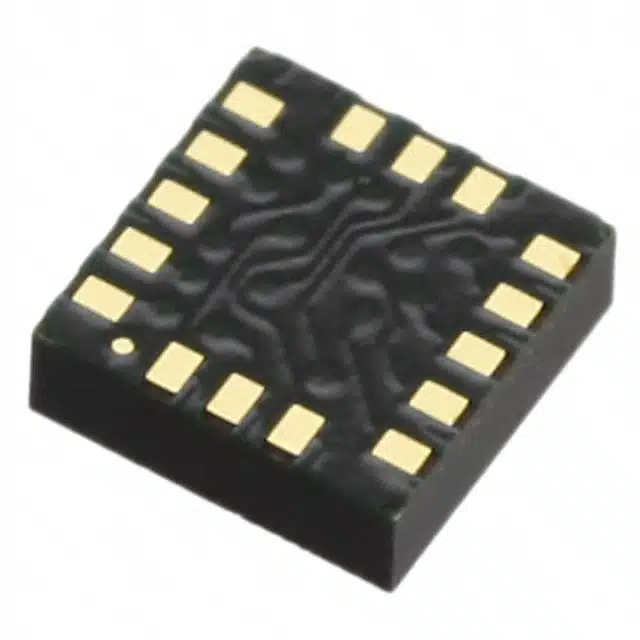
The LIS3DHTR is a high-performance, ultra-low-power 3-axis accelerometer. It offers several user-selectable scales up to 16g, allowing for flexibility in various applications. This accelerometer includes an embedded temperature sensor, which enhances its functionality by providing additional environmental data. The LIS3DHTR supports both I2C and SPI interfaces, offering versatile connectivity options for different robotic systems. Its compact design ensures easy integration into various platforms, making it ideal for projects that require precise motion sensing.
Technical Specifications of the LIS3DHTR
The LIS3DHTR boasts impressive technical specifications that make it suitable for a wide range of applications. It operates within a temperature range of -40 to +85 °C, ensuring reliable performance in diverse environments. The sensor features a 10-bit ADC, which provides accurate data conversion for precise measurements. Additionally, it includes programmable thresholds and timing for interrupt generators, enabling real-time responsiveness in robotic applications. The triple-axis accelerometer also comes with a 32-level FIFO buffer, allowing efficient data storage and processing. These specifications highlight the LIS3DHTR‘s capability to enhance robotic systems by providing accurate and reliable motion data.
Setting Up the LIS3DHTR Sensor
Setting up the LIS3DHTR sensor involves gathering the necessary components and integrating them into a circuit. This process ensures that the accelerometer functions correctly within a robotics project.
Required Components for Integration
To integrate the LIS3DHTR sensor, gather the following components:
-
LIS3DHTR Sensor Module: The primary component for motion detection.
-
Microcontroller or Raspberry Pi: Acts as the brain of the project, processing data from the sensor.
-
Connecting Wires: Facilitates connections between the sensor and the microcontroller.
-
Breadboard: Provides a platform for assembling the circuit without soldering.
-
Power Supply: Powers the entire setup, ensuring the sensor and microcontroller operate efficiently.
These components form the foundation for integrating the LIS3DHTR into a robotics project.
Circuit Integration with the LIS3DHTR
Integrating the LIS3DHTR sensor into a circuit involves connecting it to a microcontroller or Raspberry Pi. Follow these steps for successful integration:
-
Position the Sensor: Place the LIS3DHTR on the breadboard. Ensure it is stable and accessible for connections.
-
Connect Power and Ground: Attach the sensor’s VCC pin to the power supply and the GND pin to the ground. This step powers the sensor.
-
Establish Communication: Use the I2C interface for communication. Connect the sensor’s SDA (data line) and SCL (clock line) pins to the corresponding I2C pins on the Raspberry Pi. This connection enables data transfer between the sensor and the microcontroller.
-
Verify Connections: Double-check all connections. Ensure wires are secure and correctly placed to prevent errors during operation.
-
Test the Setup: Power the circuit and test the sensor’s functionality. Use simple scripts on the Raspberry Pi to verify data readings from the accelerometer.
These steps ensure the LIS3DHTR sensor integrates seamlessly into the circuit, ready for programming and data collection.
Programming the LIS3DHTR Sensor
Programming the LIS3DHTR sensor involves writing code to read and interpret data from the accelerometer. This process allows developers to utilize the sensor’s capabilities in their robotics projects effectively.
Example Code for LIS3DHTR
To get started with programming the LIS3DHTR, developers can use an example code for Arduino. This code demonstrates how to read data from the accelerometer using the I2C interface. Below is a simple script that can be used with a Raspberry Pi:
#include <Wire.h>
#include <LIS3DHTR.h>

LIS3DHTR<TwoWire> lis;

void setup() {
  Serial.begin(9600);
  Wire.begin();
  lis.begin(Wire, 0x18); // Initialize the LIS3DHTR sensor
  lis.setOutputDataRate(LIS3DHTR_DATARATE_50HZ); // Set data rate
}

void loop() {
  if (lis.available()) {
    float x = lis.getAccelerationX();
    float y = lis.getAccelerationY();
    float z = lis.getAccelerationZ();
    Serial.print("X: "); Serial.print(x);
    Serial.print(" Y: "); Serial.print(y);
    Serial.print(" Z: "); Serial.println(z);
  }
  delay(100);
}
This example code for Arduino initializes the LIS3DHTR sensor and reads acceleration data from the X, Y, and Z axes. The data is then printed to the serial monitor, allowing developers to observe the sensor’s output.
Libraries and Resources for the Accelerometer
Several libraries and resources are available to assist with programming the LIS3DHTR accelerometer. These libraries simplify the process of interfacing with the sensor and retrieving data. One popular library is the Adafruit LIS3DH library, which provides functions for configuring and reading data from the accelerometer. This library supports both Arduino and Raspberry Pi platforms, making it versatile for various projects.
For those using a Raspberry Pi, Python can be used to program the LIS3DHTR. The smbus library in Python facilitates communication with the sensor over the I2C interface. Developers can find numerous online tutorials and resources to guide them through the process of setting up and programming the LIS3DHTR with Python.
By utilizing these libraries and resources, developers can efficiently integrate the LIS3DHTR into their robotics projects, enabling precise motion control and data analysis.
Best Practices for LIS3DHTR Integration
Integrating the LIS3DHTR into a robotics project requires careful attention to detail. Following best practices ensures that the sensor provides accurate and reliable data, enhancing the overall performance of the robotic system.
Calibration Techniques for Accurate Data
Calibration is crucial for obtaining precise readings from the 3-axis accelerometer. Proper calibration aligns the sensor’s output with real-world measurements, ensuring accuracy in motion tracking and control. Here are some effective calibration techniques:
-
Positioning: Place the accelerometer as close as possible to the center of mass of the object being measured. This positioning minimizes errors caused by rotational forces.
-
Static Calibration: Use a known reference position to calibrate the sensor. For instance, place the sensor on a flat surface and record the output. Adjust the readings to match the expected values for that position.
-
Dynamic Calibration: Move the sensor through known motions and compare the output to expected results. This method helps in fine-tuning the sensor’s response to dynamic changes.
-
Wavelet Threshold Denoising: Apply denoising techniques to filter out noise from the sensor’s signal. This approach enhances sensitivity and accuracy, as demonstrated in studies comparing different denoising methods.
By implementing these calibration techniques, developers can ensure that the LIS3DHTR provides accurate data for motion control and analysis.
Data Interpretation from the 3-axis Accelerometer
Interpreting data from the 3-axis accelerometer involves understanding the sensor’s output and translating it into meaningful information. Here are some tips for effective data interpretation:
-
Axis Understanding: The triple-axis accelerometer measures acceleration along three perpendicular axes: X, Y, and Z. Each axis provides data on the sensor’s orientation and movement.
-
Data Conversion: Use the Adafruit LIS3DH library or similar resources to convert raw data into readable units. This conversion simplifies the process of analyzing the sensor’s output.
-
I2C Communication: Utilize the I2C interface for efficient data transfer between the sensor and the Raspberry Pi. This communication method ensures that data is transmitted accurately and quickly.
-
Python Programming: Leverage Python scripts to automate data collection and analysis. Python’s versatility makes it an ideal choice for processing data from the LIS3DHTR.
-
Real-time Monitoring: Implement real-time monitoring to observe changes in acceleration and motion. This practice helps in identifying patterns and anomalies in the sensor’s output.
By following these best practices, developers can effectively integrate the LIS3DHTR into their robotics projects, ensuring precise motion tracking and control.
Troubleshooting Common Issues with LIS3DHTR
When integrating the LIS3DHTR sensor into a robotics project, developers may encounter some common issues. Addressing these problems ensures that the sensor functions optimally, providing accurate data for motion control and analysis.
Sensor Not Responding
If the LIS3DHTR sensor does not respond, several factors might be at play. Follow these steps to diagnose and resolve the issue:
-
Check Power Supply: Ensure that the sensor receives adequate power. Verify connections between the power source and the sensor’s VCC and GND pins. A stable power supply is crucial for the sensor’s operation.
-
Inspect I2C Connections: Examine the I2C connections between the sensor and the Raspberry Pi. Confirm that the SDA and SCL lines are correctly connected. Loose or incorrect connections can prevent communication.
-
Verify I2C Address: The sensor’s I2C address must match the one specified in the code. Double-check the address in the code and ensure it aligns with the sensor’s default or configured address.
-
Test with Simple Code: Use a basic script to test the sensor’s responsiveness. This approach helps identify whether the issue lies within the code or the hardware setup.
-
Examine Raspberry Pi Configuration: Ensure that the Raspberry Pi’s I2C interface is enabled. Access the Raspberry Pi configuration settings and verify that I2C is active.
By following these steps, developers can troubleshoot and resolve issues related to the sensor not responding.
Inaccurate Readings from the Accelerometer
Inaccurate readings from the accelerometer can affect the performance of a robotics project. Consider these solutions to improve data accuracy:
-
Calibrate the Sensor: Calibration aligns the sensor’s output with real-world measurements. Use static and dynamic calibration techniques to enhance accuracy.
-
Reduce Noise: Implement denoising techniques to filter out unwanted noise from the sensor’s signal. This step improves the precision of acceleration data.
-
Stabilize the Setup: Ensure that the sensor is securely mounted. Unstable positioning can lead to erroneous readings due to vibrations or movement.
-
Check for Interference: External electromagnetic interference can affect sensor readings. Keep the sensor away from sources of interference, such as motors or other electronic components.
-
Review Code Logic: Inspect the code for any logical errors that might affect data interpretation. Ensure that the code correctly processes and displays the sensor’s output.
By addressing these factors, developers can achieve accurate and reliable readings from the LIS3DHTR accelerometer, enhancing the effectiveness of motion control in their robotics projects.
Example Projects Using LIS3DHTR
The LIS3DHTR sensor opens up a world of possibilities for robotics enthusiasts. By integrating this 3-axis accelerometer into various projects, developers can explore both simple and advanced applications. The following examples demonstrate how the LIS3DHTR enhances robotic capabilities.
Simple Robotics Applications with LIS3DHTR
-
Balancing Robot: A balancing robot uses the LIS3DHTR to maintain stability. The sensor detects tilt and acceleration, allowing the robot to adjust its position. Developers can use a Raspberry Pi to process data from the triple-axis accelerometer, ensuring real-time balance control.
-
Gesture-Controlled Car: This project involves controlling a small car with hand gestures. The LIS3DHTR senses motion and orientation changes. A Raspberry Pi interprets these signals to drive the car forward, backward, or sideways. This application showcases the sensor’s ability to translate human gestures into robotic actions.
-
Tilt-Activated Light: In this project, the LIS3DHTR triggers a light when tilted. The sensor detects changes in orientation, and a Raspberry Pi processes the data to activate the light. This simple application demonstrates how the 3-axis accelerometer can enhance interactive projects.
Advanced Robotics Projects Utilizing the Accelerometer
-
Drone Navigation System: Integrating the LIS3DHTR into a drone enhances its navigation capabilities. The sensor provides precise motion data, allowing the drone to maintain stability and navigate complex environments. A Raspberry Pi processes the accelerometer’s output, ensuring accurate flight control.
-
Robotic Arm with Feedback Control: This project involves a robotic arm that uses the LIS3DHTR for feedback control. The sensor monitors the arm’s movement, providing data on its position and orientation. A Raspberry Pi processes this information, enabling precise control and adjustments. This application highlights the sensor’s role in enhancing robotic precision.
-
Autonomous Vehicle: An autonomous vehicle equipped with the LIS3DHTR can navigate obstacles and maintain balance. The sensor detects changes in acceleration and orientation, while a Raspberry Pi processes the data to guide the vehicle. This advanced project demonstrates the sensor’s potential in developing intelligent robotic systems.
These projects illustrate the versatility of the LIS3DHTR in enhancing robotic applications. By leveraging the capabilities of this 3-axis accelerometer, developers can create innovative solutions that push the boundaries of robotics.
Integrating the LIS3DHTR into robotics projects offers significant advantages. The sensor enhances robotic capabilities by providing precise motion detection and orientation data. Developers can leverage its features to create innovative applications. The Raspberry Pi serves as an excellent platform for processing data from the sensor, enabling real-time analysis and control. Experimenting with the LIS3DHTR in various projects encourages creativity and innovation. Its impact on advancing robotics is profound, paving the way for more sophisticated and responsive robotic systems.
FAQ
How to use the LIS3DH accelerometer in projects?
The LIS3DH accelerometer enhances projects by adding translation detection. This triple-axis accelerometer, also known as a 3DoF device, features analog inputs and built-in movement detection capabilities. Developers can integrate it into various applications to measure acceleration along three axes, providing valuable data for motion analysis.
What are the voltage requirements for the LIS3DH?
The LIS3DH operates at a voltage of 3.3V. Supplying voltages greater than approximately 3.6V can cause permanent damage to the integrated circuit. It is crucial to use a 3.3V supply output to ensure the sensor functions correctly and remains undamaged.
Can the LIS3DHTR be used with both Arduino and Raspberry Pi?
Yes, the LIS3DHTR can be used with both Arduino and Raspberry Pi platforms. Libraries such as the Adafruit LIS3DH library support these platforms, simplifying the process of interfacing with the sensor and retrieving data. This versatility allows developers to choose the platform that best suits their project needs.
What interfaces does the LIS3DHTR support?
The LIS3DHTR supports both I2C and SPI interfaces. These interfaces provide flexible connectivity options for different robotic systems. Developers can select the interface that aligns with their project’s requirements, ensuring efficient communication between the sensor and the microcontroller.
How do you calibrate the LIS3DHTR for accurate data?
Calibration ensures the LIS3DHTR provides precise readings. Developers can use static calibration by placing the sensor on a flat surface and adjusting the output to match expected values. Dynamic calibration involves moving the sensor through known motions and fine-tuning its response. These techniques align the sensor’s output with real-world measurements.
What are some common issues when using the LIS3DHTR?
Common issues include the sensor not responding and inaccurate readings. To troubleshoot, check the power supply, inspect I2C connections, and verify the I2C address. For inaccurate readings, calibrate the sensor, reduce noise, and stabilize the setup. Addressing these factors ensures optimal sensor performance.
How does the LIS3DHTR enhance robotics projects?
The LIS3DHTR enhances robotics projects by providing precise motion detection and orientation data. Its compact design and versatile connectivity options make it ideal for integration into various robotic platforms. The sensor’s real-time data capabilities improve balance control, navigation, and gesture recognition in robotic systems.
What are some example projects using the LIS3DHTR?
Example projects include a balancing robot, a gesture-controlled car, and a tilt-activated light. Advanced applications involve drone navigation systems, robotic arms with feedback control, and autonomous vehicles. These projects demonstrate the sensor’s versatility in enhancing robotic capabilities.
Where can developers find resources for programming the LIS3DHTR?
Developers can find resources for programming the LIS3DHTR in libraries like the Adafruit LIS3DH library. Online tutorials and guides provide step-by-step instructions for setting up and programming the sensor with platforms like Arduino and Raspberry Pi. These resources simplify the integration process and enable developers to leverage the sensor’s full potential.
See Also
Boost Robotics Efficiency by Integrating AEAT-8800-Q24
Simple Guide to Integrate SN74LVC4245APW Sensors
Using STM32F103C8T6 for Bluetooth Robot Control
Integrating ATA5824C for Effective Remote Control Solutions
Three Effective Methods to Integrate MC9S12XET512VAG