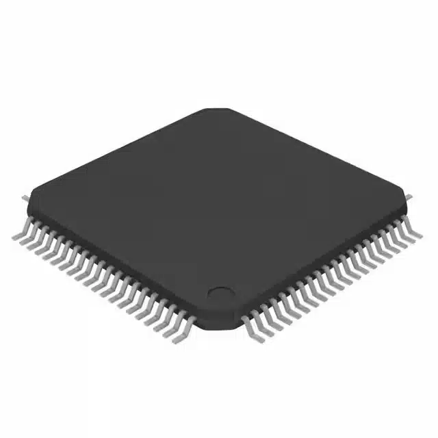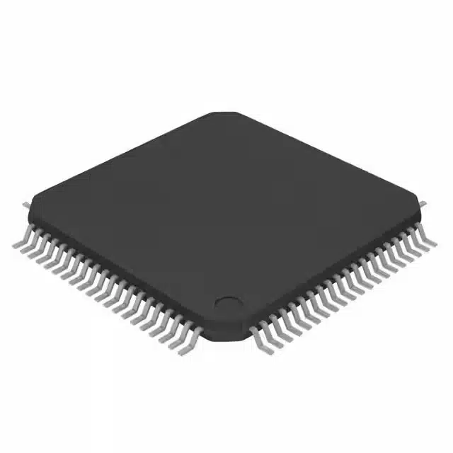
The S9KEAZ128AMLK microcontroller simplifies integration for developers by offering a streamlined process. It begins with hardware setup, where power connections and pin configurations ensure stability. Software configuration follows, enabling the installation of essential tools and drivers. Programming unlocks its potential, allowing users to write and upload code tailored to their applications. Testing validates functionality and performance, ensuring reliability. With its robust ARM® Cortex®-M0+ core and versatile peripherals, this microcontroller adapts seamlessly to automotive, industrial, and embedded systems, making it a reliable choice for diverse projects.
Key Takeaways
-
Start with a solid hardware setup by ensuring stable power connections and proper pin configurations to prevent damage and ensure reliable operation.
-
Utilize recommended tools like the FRDM-KEAZ128 development platform to simplify the integration process and reduce setup time.
-
Choose a compatible Integrated Development Environment (IDE) such as NXP’s CodeWarrior or MCUXpresso for efficient software configuration and programming.
-
Follow best practices for debugging, including testing incrementally and using descriptive comments to streamline the identification of issues.
-
Conduct thorough testing and validation to ensure the microcontroller operates as intended, focusing on power, clock functionality, and communication protocols.
-
Be proactive in addressing common challenges such as incorrect pin connections and IDE setup errors to avoid delays in the integration process.
-
Leverage the S9KEAZ128AMLK’s versatile features and robust performance to create innovative solutions across automotive, industrial, and embedded applications.
Overview of the S9KEAZ128AMLK
The S9KEAZ128AMLK microcontroller stands out as a versatile and efficient solution for developers. Its design focuses on delivering robust performance while maintaining cost-effectiveness. Built around the ARM® Cortex®-M0+ processor, it operates at speeds of up to 48 MHz. This balance between processing power and energy efficiency makes it ideal for a wide range of applications.
Key Features of the S9KEAZ128AMLK
ARM® Cortex®-M0+ core and performance capabilities
At the core of the S9KEAZ128AMLK lies the ARM® Cortex®-M0+ processor. It provides a reliable foundation for handling complex tasks with ease. Operating at up to 48 MHz, it ensures smooth execution of operations while keeping power consumption low. This feature makes it suitable for applications requiring both performance and efficiency.
Integrated peripherals and automotive-grade reliability
The microcontroller integrates a variety of peripherals, enhancing its functionality. These include timers, analog-to-digital converters (ADCs), and flexible GPIOs. Its automotive-grade reliability ensures consistent performance in demanding environments, such as automotive systems and industrial automation.
Communication interfaces (UART, SPI, I²C) and GPIO support
The S9KEAZ128AMLK supports multiple communication protocols, including UART, SPI, and I²C. These interfaces enable seamless data exchange between devices. Additionally, its configurable GPIOs provide flexibility for connecting sensors, actuators, and other components, making it adaptable to diverse project requirements.
Applications of the S9KEAZ128AMLK
Automotive systems (e.g., body control modules, immobilizers)
The S9KEAZ128AMLK excels in automotive applications. It powers body control modules, managing functions like lighting and window controls. It also supports immobilizers, enhancing vehicle security. Its reliability and performance make it a trusted choice for automotive manufacturers.
Industrial automation (e.g., motor controllers, PLCs)
In industrial settings, the microcontroller plays a key role in automation. It efficiently controls motors in equipment and appliances. Programmable Logic Controllers (PLCs) benefit from its precise timing and control capabilities. Its robust design ensures durability in harsh industrial environments.
Consumer electronics and IoT devices
The S9KEAZ128AMLK finds applications in consumer electronics and IoT devices. It serves as the central controller for smart home systems and connected devices. Its low power consumption and versatile features make it ideal for wearables and other compact, battery-operated gadgets.
Step-by-Step Integration Process
Hardware Setup
Connecting the microcontroller to power and ground
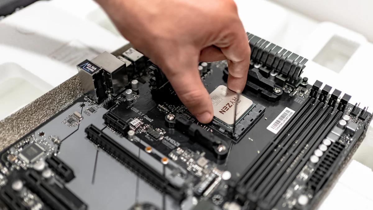
The first step in integrating the S9KEAZ128AMLK involves establishing a stable power supply. Connect the microcontroller’s VDD pin to a regulated power source, ensuring it matches the voltage requirements specified in the datasheet. Ground the VSS pin to complete the circuit. Proper power and ground connections are critical for reliable operation and to prevent damage to the device.
Pin configuration and peripheral connections
Next, configure the pins based on the project requirements. Assign pins for GPIO, communication interfaces (UART, SPI, I²C), and other peripherals. Refer to the microcontroller’s pinout diagram to identify the appropriate pins for each function. Secure connections to external components, such as sensors or actuators, to ensure seamless data exchange and control.
Recommended tools (e.g., FRDM-KEAZ128 development platform)
Using the right tools simplifies the hardware setup process. The FRDM-KEAZ128 development platform, designed specifically for the S9KEAZ128AMLK, provides a convenient way to test and prototype applications. This platform includes onboard debugging capabilities and pre-configured pin headers, reducing setup time and effort.
Software Setup
Installing the IDE (e.g., NXP’s CodeWarrior or MCUXpresso)
Begin the software setup by installing an Integrated Development Environment (IDE) compatible with the S9KEAZ128AMLK. NXP’s CodeWarrior and MCUXpresso are popular choices. These IDEs offer user-friendly interfaces and robust debugging tools, making them ideal for microcontroller development.
Downloading and setting up SDKs and drivers
Download the Software Development Kit (SDK) and drivers for the microcontroller from NXP’s official website. The SDK includes libraries, example projects, and documentation tailored to the S9KEAZ128AMLK. Install these resources in the IDE to streamline the development process and ensure compatibility with the hardware.
Configuring the development environment
Configure the IDE to match the microcontroller’s specifications. Set the target device to S9KEAZ128AMLK and verify that the correct SDK is loaded. Adjust compiler settings and debugging options as needed. A properly configured environment minimizes errors during programming and testing.
Configuration
Setting up the clock and power modes
Configure the microcontroller’s clock system to achieve optimal performance. Select the desired clock source and frequency using the IDE’s configuration tools. Adjust power modes to balance energy efficiency and processing speed, depending on the application’s requirements.
Initializing GPIOs and other peripherals
Initialize the GPIOs and peripherals to prepare the microcontroller for operation. Define the input/output direction for each GPIO pin and set initial states. Enable and configure peripherals, such as ADCs or timers, to match the project’s functional needs.
Configuring communication protocols (e.g., UART, SPI, I²C)
Set up communication protocols to enable data exchange between the microcontroller and external devices. Configure UART, SPI, or I²C interfaces by specifying parameters like baud rate, data format, and clock polarity. Test the communication channels to ensure proper functionality before proceeding to the programming phase.
Programming and Debugging
Writing and uploading code to the microcontroller
Programming the S9KEAZ128AMLK begins with writing application-specific code. Developers should use a compatible Integrated Development Environment (IDE) such as NXP’s CodeWarrior or MCUXpresso. These tools provide a structured workspace for creating, editing, and managing code. The IDE allows developers to write programs in C or assembly language, which are commonly used for microcontroller development.
Once the code is ready, the next step involves uploading it to the microcontroller. This process requires a hardware interface, such as the FRDM-KEAZ128 development platform or the TRK-KEA128 board. These tools connect the microcontroller to the computer via USB, enabling seamless code transfer. Developers should ensure that the microcontroller is powered correctly and that the IDE recognizes the connected device. After uploading, the microcontroller executes the program, bringing the application to life.
Using debugging tools (e.g., TRK-KEA128 board) to identify and fix issues
Debugging is an essential part of the development process. It helps identify and resolve errors in the code or hardware setup. The TRK-KEA128 board serves as a valuable tool for debugging the S9KEAZ128AMLK. This board includes built-in debugging features, such as breakpoints and step-by-step execution, which allow developers to analyze the program’s behavior in real time.
To begin debugging, developers should connect the TRK-KEA128 board to the microcontroller and the IDE. The IDE provides a debugging interface where developers can monitor variables, inspect memory, and evaluate register values. By using these features, they can pinpoint the source of issues, such as incorrect logic or misconfigured peripherals. Debugging tools also enable developers to test specific sections of code without running the entire program, saving time and effort.
Best practices for efficient debugging
Efficient debugging requires a systematic approach. Developers should follow best practices to streamline the process and minimize downtime:
-
Start with simple checks: Verify basic connections, such as power supply and pin configurations, before diving into complex debugging.
-
Use descriptive comments: Annotate the code with clear comments to explain its functionality. This practice makes it easier to identify potential errors during debugging.
-
Test incrementally: Break the program into smaller sections and test each one individually. This approach isolates issues and simplifies troubleshooting.
-
Leverage debugging tools: Utilize the IDE’s debugging features, such as watchpoints and variable tracking, to gain insights into the program’s execution.
-
Document findings: Keep a record of identified issues and their solutions. This documentation serves as a reference for future projects and helps avoid repeating mistakes.
By adhering to these practices, developers can efficiently debug the S9KEAZ128AMLK and ensure the microcontroller operates as intended.
Testing and Validation
Testing and validation ensure the S9KEAZ128AMLK microcontroller operates as intended. This phase verifies functionality, integration, and performance under various conditions. Developers should follow a structured approach to identify and resolve potential issues.
Functional Testing
Verifying power and clock functionality
Power and clock systems form the foundation of the microcontroller’s operation. Developers should begin by confirming that the power supply delivers the correct voltage to the microcontroller. Using a multimeter, they can measure the voltage at the VDD and VSS pins to ensure compliance with the datasheet specifications. The clock system requires validation to confirm it generates the desired frequency. Tools like oscilloscopes help monitor the clock signal and verify its stability. These steps ensure the microcontroller receives reliable power and timing for proper operation.
Testing GPIOs and peripheral connections
GPIOs and peripherals play a critical role in interfacing with external components. Developers should test each GPIO pin to confirm it functions as expected. Configuring pins as inputs or outputs and observing their behavior under different conditions helps validate their functionality. Peripheral connections, such as ADCs or timers, require testing to ensure they operate correctly. For example, developers can input a known analog signal to the ADC and verify the digital output matches the expected value. Testing these components ensures seamless communication and control within the project.
Integration Testing
Ensuring compatibility with other components in the project
Integration testing evaluates how the microcontroller interacts with other components in the system. Developers should connect the S9KEAZ128AMLK to sensors, actuators, or other devices and observe their behavior. Compatibility issues, such as mismatched voltage levels or incorrect communication protocols, may arise during this phase. Addressing these issues ensures the microcontroller integrates smoothly into the overall system.
Running test cases for communication protocols
Communication protocols like UART, SPI, and I²C enable data exchange between the microcontroller and external devices. Developers should create test cases to evaluate these protocols. For instance, they can send and receive data packets over UART and verify the integrity of the transmitted information. Testing SPI and I²C involves checking parameters like clock speed and data format. Running these test cases ensures reliable communication and prevents data loss or corruption.
Performance Validation
Measuring power consumption and response times
Performance validation assesses the microcontroller’s efficiency and responsiveness. Developers should measure power consumption under different operating conditions using a power analyzer. Comparing these measurements to the datasheet values helps confirm energy efficiency. Response times, such as the delay between input and output signals, require evaluation to ensure the microcontroller meets application requirements. Tools like logic analyzers assist in capturing and analyzing these timings.
Stress testing under different conditions
Stress testing evaluates the microcontroller’s reliability under extreme conditions. Developers should expose the S9KEAZ128AMLK to varying temperatures, voltages, and workloads to observe its behavior. For example, running the microcontroller at maximum clock speed while executing complex tasks tests its stability. Identifying potential failure points during stress testing helps improve the system’s robustness and ensures long-term reliability.
Common Challenges and Solutions
Hardware Challenges
Incorrect pin connections or power supply issues
Incorrect pin connections often lead to malfunctioning circuits. Developers must double-check the microcontroller’s pinout diagram during setup. Misaligned connections between GPIO pins and external components can disrupt data flow. Using a multimeter to verify continuity ensures proper connections. Power supply issues, such as voltage mismatches, can damage the microcontroller. Developers should confirm that the power source matches the voltage requirements specified in the datasheet. Adding decoupling capacitors near the power pins helps stabilize the voltage supply.
Solutions for handling noise and interference
Noise and interference can degrade signal quality and cause erratic behavior. Shielding cables and placing the microcontroller away from high-frequency devices reduce electromagnetic interference. Proper grounding minimizes noise in sensitive circuits. Adding pull-up or pull-down resistors to input pins prevents floating states. Filtering techniques, such as using capacitors or ferrite beads, help suppress high-frequency noise. These measures ensure stable operation in noisy environments.
Software Challenges
IDE setup errors or missing drivers
Errors during IDE setup can delay development. Developers should follow the installation guide provided by the IDE vendor. Missing drivers often result in communication failures between the microcontroller and the computer. Downloading the latest drivers from the manufacturer’s website resolves compatibility issues. Verifying the IDE’s target device settings ensures proper configuration. Testing the setup with example projects confirms that the environment is ready for development.
Debugging common coding mistakes
Coding mistakes, such as syntax errors or incorrect logic, frequently occur during programming. Developers should use the IDE’s built-in code editor to identify syntax errors. Logical errors require careful review of the code’s flow and functionality. Debugging tools, such as breakpoints and variable monitoring, help locate issues. Writing modular code simplifies troubleshooting by isolating problematic sections. Peer code reviews provide an additional layer of error detection.
Integration Challenges
Communication protocol mismatches
Mismatched communication protocols disrupt data exchange between devices. Developers must ensure that both the microcontroller and external devices use the same protocol settings. For UART, verifying baud rate, parity, and stop bits prevents transmission errors. SPI requires matching clock polarity and phase settings. I²C demands consistent addressing and timing configurations. Testing each protocol with known data packets confirms compatibility.
Resolving timing and synchronization issues
Timing and synchronization issues arise when devices operate at different speeds. Developers should align clock frequencies to maintain synchronization. Adding delays or adjusting timing parameters resolves conflicts in data transmission. For real-time applications, using hardware timers ensures precise timing. Monitoring signals with an oscilloscope helps identify and correct timing discrepancies. These steps ensure smooth integration and reliable communication.
Integrating the S9KEAZ128AMLK microcontroller involves four essential steps: hardware setup, software configuration, programming, and testing. Each step ensures a seamless process, from establishing stable connections to validating performance. Developers can confidently begin their integration journey by following this structured approach. The S9KEAZ128AMLK offers unmatched versatility, making it an excellent choice for automotive, industrial, and embedded applications. Its robust features and adaptability empower developers to create innovative solutions while maintaining efficiency and reliability.
What makes the S9KEAZ128AMLK suitable for automotive applications?
The S9KEAZ128AMLK microcontroller offers automotive-grade reliability, ensuring consistent performance in demanding environments. Its integrated peripherals, such as timers and ADCs, support precise control and monitoring. Additionally, its compatibility with communication protocols like UART, SPI, and I²C enables seamless integration into automotive systems, including body control modules and immobilizers.
Can the S9KEAZ128AMLK be used for industrial automation?
Yes, the S9KEAZ128AMLK excels in industrial automation. It efficiently manages motor controllers, programmable logic controllers (PLCs), and human-machine interfaces (HMIs). Its robust design ensures durability in harsh industrial conditions, while its flexible GPIOs and communication interfaces allow easy connection to sensors and actuators.
What tools are recommended for developing with the S9KEAZ128AMLK?
Developers should consider using the FRDM-KEAZ128 development platform or the TRK-KEA128 board. These tools simplify prototyping and debugging. For software development, NXP’s CodeWarrior or MCUXpresso IDEs provide user-friendly interfaces and robust debugging features. These resources streamline the development process and enhance productivity.
How does the S9KEAZ128AMLK handle communication with other devices?
The S9KEAZ128AMLK supports multiple communication protocols, including UART, SPI, and I²C. These protocols enable reliable data exchange between the microcontroller and external devices. Developers can configure parameters like baud rate and clock polarity to ensure compatibility with connected components.
What steps should be taken to ensure proper hardware setup?
To ensure proper hardware setup, developers must connect the microcontroller’s VDD pin to a regulated power source and ground the VSS pin. Pin configurations should align with project requirements, and external components like sensors or actuators must be securely connected. Using the FRDM-KEAZ128 development platform can simplify this process.
What are the key features of the S9KEAZ128AMLK?
The S9KEAZ128AMLK features an ARM® Cortex®-M0+ core running at up to 48 MHz, 128 KB Flash memory, and 16 KB RAM. It includes multiple communication interfaces (UART, SPI, I²C), a 12-bit ADC, and up to 71 configurable GPIOs. These features make it a versatile solution for various applications.
How can developers debug their applications effectively?
Developers can use debugging tools like the TRK-KEA128 board to identify and resolve issues. The IDE’s debugging interface allows monitoring of variables, inspecting memory, and evaluating register values. Best practices include testing code incrementally, using descriptive comments, and leveraging breakpoints for efficient debugging.
What are the common challenges when integrating the S9KEAZ128AMLK?
Common challenges include incorrect pin connections, IDE setup errors, and communication protocol mismatches. Developers should double-check pin configurations, ensure the IDE is properly installed, and verify protocol settings. Addressing these issues early prevents delays and ensures smooth integration.
How does the S9KEAZ128AMLK perform under stress?
The S9KEAZ128AMLK demonstrates excellent reliability under stress. Developers can test its performance by exposing it to varying temperatures, voltages, and workloads. Measuring power consumption and response times under these conditions confirms its stability and efficiency.
Why should developers choose the S9KEAZ128AMLK for their projects?
The S9KEAZ128AMLK offers a powerful and flexible solution for automotive, industrial, and embedded applications. Its robust features, including an ARM® Cortex®-M0+ core and versatile peripherals, ensure high performance and adaptability. Developers benefit from its cost-effectiveness, reliability, and ease of integration, making it an ideal choice for diverse projects.
See Also
Three Effective Methods for MC9S12XET512VAG Integration
Unveiling the Essential Specifications of MC9S12XEQ512CAL
Integrating AEAT-8800-Q24 to Boost Robotics Efficiency
Key Programming Tips for MC9S12XD256 Microcontrollers
A Deep Dive into MC9S12DJ256MFUE Automotive Specs
