The TCA6507PWR LED Driver plays a critical role in modern LED systems by providing efficient power management and precise control over LED current. Designed for diverse lighting applications, it simplifies the operation of high-power LED setups while ensuring reliable performance. This driver integrates seamlessly with the I2C interface, enabling advanced dimming and RGB lighting effects without overburdening the microcontroller. Its energy-efficient design reduces power consumption, making it ideal for both battery-powered and large-scale installations. Proper installation of the TCA6507PWR ensures optimal functionality, enhancing the performance and lifespan of LED systems across various applications.
Key Takeaways
-
The TCA6507PWR LED Driver helps manage power and control LEDs well. It works great for many uses.
-
Installing it correctly is very important. Check the datasheet for pin details and make sure all parts work together to avoid problems.
-
Use basic tools like a soldering iron, multimeter, and wire cutters to make strong connections and check measurements while building.
-
Stay safe by turning off power before wiring and using tools with insulation to avoid accidents and keep things working right.
-
Test and check the system often after setting it up. This keeps it working well and fixes any problems quickly.
Tools and Materials for Integrating the TCA6507PWR
Essential Tools
Soldering iron and solder
A soldering iron is necessary for creating secure electrical connections in the LED driver circuit. Use high-quality solder to ensure reliable joints. This tool is essential for attaching components like the TCA6507PWR IC to a breadboard or PCB.
Multimeter
A multimeter helps measure voltage, current, and resistance in the circuit. It ensures that the LED driver operates as expected and verifies the connections during assembly.
Wire strippers and screwdrivers
Wire strippers are used to remove insulation from wires, enabling proper connections. Screwdrivers assist in securing components and tightening screws on the PCB or enclosure.
Required Components
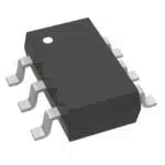
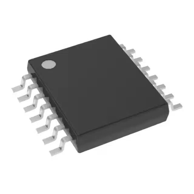
TCA6507PWR LED Driver IC
The TCA6507PWR is the core component of the system. Its compact design (4.4mm width, 1mm thickness) and high efficiency (operating at 400 kHz) make it ideal for LED lighting applications. It supports up to 40mA per channel and operates within a flexible power supply range of 1.8V to 3.6V.
|
Specification |
Details |
|---|---|
|
High Efficiency |
Operates at 400 kHz |
|
Compact Design |
4.4mm width, 1mm thickness |
|
Robust Output |
Up to 40mA per channel |
|
Flexible Power Supply |
1.8V to 3.6V |
|
Low Power Consumption |
Max supply current of 25μA |
|
Compliance |
ROHS3 compliant, lead-free |
|
Operating Temperature Range |
-40°C to 125°C |
Compatible LEDs
Choose LEDs that match the driver’s specifications. The TCA6507PWR supports various LED types, making it suitable for applications requiring a constant current source.
Resistors, capacitors, and other passive components
These components stabilize the circuit and ensure smooth operation. Resistors help regulate current, while capacitors filter noise in the power supply.
Power supply matching the driver’s specifications
A power supply within the 1.8V to 3.6V range is essential. It ensures the IC functions efficiently and provides a stable constant current source for the LEDs.
Breadboard or PCB for prototyping
A breadboard allows for quick prototyping and testing of the LED driver circuit. For permanent installations, use a PCB to secure components and improve durability.
Safety Precautions for Working with LED Drivers
Electrical Safety Guidelines
Working with LED drivers requires strict adherence to electrical safety guidelines to prevent accidents and ensure proper functionality. Following these precautions minimizes risks:
-
Disconnect the power supply before making any wiring changes. This step eliminates the risk of electric shock or short circuits.
-
Use insulated tools to handle electrical components. Insulated tools protect against accidental contact with live circuits.
-
Look for certifications like UL, CE Marking, ENEC Mark, or FCC Compliance on the LED driver. These certifications indicate that the product has undergone rigorous testing for electrical safety and performance.
Handling the TCA6507PWR and Components
Proper handling of the TCA6507PWR and its components is essential to maintain their integrity and functionality.
-
Ground yourself using an anti-static wrist strap or mat before touching the IC. Static discharge can damage sensitive electronic components.
-
Handle the TCA6507PWR IC carefully by its edges. Avoid touching the pins or exposed circuitry to prevent contamination or physical damage.
Workspace Safety Tips
A safe workspace ensures smooth assembly and reduces hazards during the integration process.
-
Work in a well-ventilated area when soldering. Soldering produces fumes that can be harmful if inhaled. Adequate ventilation protects the user’s health.
-
Keep flammable materials away from the workspace. Soldering irons and other tools generate heat, which can ignite nearby flammable objects.
Tip: Always double-check connections and component placements before powering the circuit. This practice enhances safety and prevents potential damage to the LED driver or other components.
By following these safety precautions, users can ensure a secure and efficient integration process for the TCA6507PWR LED driver.
Step-by-Step Guide to Integrating the TCA6507PWR LED Driver
Preparation
Review the TCA6507PWR datasheet for pin configurations and specifications.
Before starting the installation, reviewing the TCA6507PWR datasheet is essential. The datasheet provides detailed information about the pin configurations, power requirements, and operational specifications. This step ensures that the driver is wired correctly and functions as intended. Understanding the datasheet also helps in planning the circuit layout effectively.
Gather all tools and components in a clean workspace.
Organizing tools and components in a clean workspace improves efficiency and reduces errors during installation. Follow these best practices:
-
Define clear objectives for the integration process.
-
Develop a strategy that outlines the required tools and methodologies.
-
Analyze the system to identify dependencies and functionalities.
-
Communicate the plan to all involved stakeholders.
Additionally, document and review the current processes to ensure alignment with the integration goals. Implement the plan iteratively, refining it based on results.
Wiring the TCA6507PWR
Connect the power supply to the driver’s input pins.
Turn off the power before wiring the LED driver. Connect the input wires from the power supply to the designated input pins on the TCA6507PWR. Ensure the power supply voltage falls within the 1.8V to 3.6V range for optimal performance.
Wire the LEDs to the driver’s output pins as per the datasheet.
Attach the output wires from the driver to the LED fixtures. The TCA6507PWR supports up to seven outputs, allowing for precise control of RGB lighting patterns. Refer to the datasheet for the correct pin assignments to avoid errors.
Add resistors or capacitors for stability if required.
Incorporate resistors to regulate current and capacitors to filter noise in the circuit. These components enhance stability and ensure smooth operation of the LED driver.
Configuring the LED Driver
Program the driver (if applicable) for desired LED patterns or brightness.
The TCA6507PWR supports advanced programming options through its I2C interface. Users can configure the driver for specific lighting effects, such as blinking, fading, or PWM dimming. The table below highlights key programming features:
|
Feature |
Description |
|---|---|
|
LED Driver Outputs |
Seven outputs for ON, OFF, Blinking, and Fading |
|
Programmable Blink Rates |
Yes |
|
Fade-ON and Fade-OFF Rates |
Yes |
|
Maximum Intensity Control |
16 steps from Fully-OFF to Fully-ON |
|
Smooth Transitions |
Yes, for Fade-ON and Fade-OFF |
|
Interface |
Programmed through I2C Bus Interface |
Test connections with a multimeter to ensure proper wiring.
Use a multimeter to verify all connections in the circuit. Check for continuity and ensure that the power supply delivers the correct voltage to the driver. Testing connections before powering the system prevents potential damage to the components.
Tip: Briefly power on the system after wiring to confirm functionality. Perform a final safety check and clean the workspace before proceeding to the next steps.
Testing and Final Assembly
Power on the system and verify LED functionality.
After completing the wiring and configuration, power on the system to test the functionality of the LEDs. Observe each LED to ensure it lights up as expected. Verify that the brightness levels and patterns match the programmed settings. If the LEDs do not function correctly, check the connections for loose wires or incorrect placements. Use a multimeter to confirm that the power supply delivers the correct voltage to the LED driver. This step ensures the installation process has been executed properly and the system operates efficiently.
Troubleshoot any issues before finalizing the assembly.
If the LEDs fail to perform as intended, follow these troubleshooting steps:
-
Ensure dimmer switches are compatible with the LEDs to prevent flickering.
-
Check for voltage drops that may cause inconsistent brightness.
-
Replace any burnt-out LEDs and inspect the driver for potential faults.
-
Verify that all connections are secure and free from corrosion or fraying.
-
Confirm the power supply provides adequate voltage and current.
Additionally, inspect the LEDs for physical damage or corrosion on their leads. Tighten any loose connections and ensure proper ventilation to prevent overheating. These measures help identify and resolve issues early, ensuring a smooth installation process.
Tip: Always test the system in a controlled environment to minimize risks and ensure safety during troubleshooting.
Secure components on a PCB or enclosure for durability.
Once the system functions correctly, secure all components on a PCB or within an enclosure. Handle the PCB carefully to avoid static damage or physical stress. Conduct a thorough inspection to ensure all connections are intact and the assembly is free from defects. Use screws or adhesive mounts to fix the PCB inside the enclosure. This step protects the components from external damage and enhances the durability of the installation. Properly securing the components ensures the system remains reliable over time, even in demanding environments.
Note: A well-secured assembly reduces the risk of damage during transportation or operation.
By following these steps, users can complete the installation of the TCA6507PWR LED driver with confidence, ensuring a safe and efficient lighting system.
Troubleshooting Common Issues in LED Lighting Systems
Resolving Flickering LEDs
Check for loose connections or insufficient power supply.
Flickering LEDs often result from unstable power or poor connections. Common causes include:
-
Fluctuations in the power supply.
-
Inadequate dimmer switches.
-
Overloading or incompatible electrical systems.
To resolve these issues, ensure the power supply has sufficient capacity for the LED load. A reliable power supply with 20-30% higher wattage than the total LED load prevents flickering. Additionally, inspect connections for looseness or corrosion. Proper ventilation around the power supply also helps maintain stability.
Verify resistor values and driver configuration.
Incorrect resistor values or improper driver settings can cause inconsistent LED current, leading to flickering. Verify that resistors match the circuit requirements and stabilize the current flow. Review the LED driver configuration to ensure compatibility with the lighting system. For RGB lighting, confirm that the driver supports the desired patterns and brightness levels.
Addressing Overheating Problems
Ensure proper heat dissipation with heatsinks or ventilation.
Overheating in LED systems can damage components and reduce efficiency. Heat sinks play a vital role in dissipating heat by conducting it away from the LED and circuit board. Mounting heat sinks directly onto heat-dissipating surfaces ensures even heat distribution. Active cooling options, such as fans or ventilation systems, further enhance heat management. Avoid overcrowding LEDs in fixtures to allow proper airflow.
Confirm the driver operates within its rated specifications.
Operating the driver beyond its rated specifications can lead to overheating. Internal and external over-temperature protection mechanisms help prevent this issue. For example:
|
Protection Type |
Description |
|---|---|
|
Internal Over-Temperature Protection |
Uses a thermal switch or NTC thermistor to detect overheating and reduce output. |
|
External Over-Temperature Protection |
Monitors LED board temperature and lowers output current to prevent overheating. |
Adhering to the manufacturer’s recommended operating temperature ensures the longevity of high-power LED applications.
Fixing Mismatched Specifications
Double-check LED and driver compatibility.
Compatibility issues between LEDs and the driver can cause flickering, overheating, or short lifespans. Ensure the driver’s output matches the LED current and voltage requirements. For RGB lighting, confirm that the driver supports the desired color and brightness settings.
Replace components that do not meet required ratings.
Inspect all components in the circuit for compatibility. Replace incompatible dimmer switches with LED-specific models to reduce flickering. Test the power supply for consistent voltage levels suitable for the LEDs. Examine wiring connections for wear or damage. These steps ensure the circuit operates efficiently and prevents future issues.
Tip: Regularly monitor the system for signs of wear or overheating to maintain optimal performance.
Integrating the TCA6507PWR into lighting systems involves careful preparation, precise wiring, and thorough testing. Following the step-by-step guide ensures a seamless process, from connecting the power supply to configuring the LEDs for optimal performance. This LED driver offers significant advantages, including efficient control of multiple LEDs, advanced dimming capabilities, and robust performance across various conditions. Its flexibility supports a wide range of lighting applications, from smart home setups to commercial displays. By adhering to the outlined steps, users can achieve reliable and energy-efficient lighting solutions that enhance both functionality and longevity.
Tip: Regular maintenance and monitoring of the system can further extend its lifespan and ensure consistent performance.
What makes the TCA6507PWR suitable for LED lighting systems?
The TCA6507PWR provides precise control over LED brightness and patterns. Its energy-efficient design supports multiple outputs, making it ideal for applications like RGB lighting, dimming, and smart lighting systems. It ensures reliable performance across various environments.
Can the TCA6507PWR handle RGB LED configurations?
Yes, the TCA6507PWR supports RGB LED setups. It offers seven outputs for controlling individual LEDs, enabling users to create dynamic lighting effects. Its I2C interface simplifies programming for smooth transitions and custom patterns.
How does the TCA6507PWR improve energy efficiency?
The TCA6507PWR minimizes power consumption by operating at low supply currents. It regulates LED current precisely, reducing energy waste. This feature makes it suitable for battery-powered devices and large-scale installations requiring efficient lighting solutions.
What safety precautions should users follow when integrating the TCA6507PWR?
Users should disconnect the power supply before wiring and use insulated tools to prevent short circuits. Grounding oneself with an anti-static strap protects the IC from damage. A well-ventilated workspace ensures safe soldering practices.
Is the TCA6507PWR compatible with all LED types?
The TCA6507PWR works with most LED types, provided they match its voltage and current specifications. Users should verify compatibility by reviewing the datasheet and ensuring the LEDs meet the driver’s requirements for optimal performance.
See Also
Comprehensive Instructions for AD620AN in Television Power Use
Three Methods ATIC83E2 Revolutionizes Industrial Automation Processes
Implementing ATA5824C Effectively in Remote Control Applications
Three Key Strategies for Integrating MC9S12XET512VAG
Simple Guide for Integrating Sensors with SN74LVC4245APW