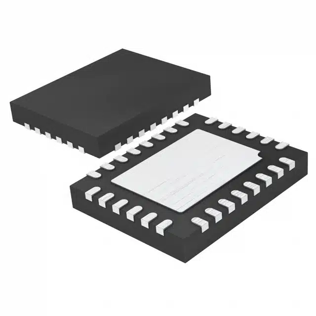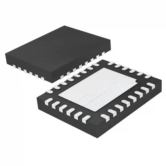
Optimizing the LTC3787EUFD#PBF ensures superior performance in boost regulator applications. This high-performance converter plays a critical role in delivering stable output voltage from lower input sources. Proper implementation enhances efficiency, reduces power losses, and improves overall system reliability. Stability becomes crucial in applications like battery-powered devices, automotive systems, and energy harvesting setups. By focusing on key design principles, engineers can unlock the full potential of this versatile component, ensuring dependable operation across a wide range of use cases.
Key Takeaways
-
Pick inductors that handle enough current to avoid overheating.
-
Use capacitors with low ESR to reduce voltage changes and keep designs stable.
-
Add a strong ground plane on your PCB to lower noise and boost performance.
-
Change feedback resistor values to get the right output voltage and steady operation.
-
Test your design in real situations to find and fix problems early.
Proper Component Selection for the LTC3787EUFD#PBF
Choosing the Right Inductor
Inductor current rating and saturation current
Selecting an inductor with the correct current rating ensures reliable operation. The inductor’s current rating must exceed the peak current of the LTC3787EUFD#PBF to prevent overheating or damage. Engineers should also consider the saturation current, which is the maximum current the inductor can handle before its inductance drops significantly. A higher saturation current provides a safety margin, especially in applications with fluctuating loads.
Selecting the appropriate inductance value
The inductance value directly affects the performance of the LTC3787EUFD#PBF. A lower inductance value increases ripple current, which can reduce efficiency. On the other hand, a higher inductance value minimizes ripple but may slow transient response. Designers should calculate the optimal inductance based on the desired output voltage, input voltage range, and switching frequency.
Selecting Capacitors
Low ESR capacitors for input and output filtering
Low ESR (Equivalent Series Resistance) capacitors are essential for minimizing voltage ripple and ensuring stable operation. For input filtering, these capacitors reduce noise from the power source. For output filtering, they smooth the voltage supplied to the load. Ceramic capacitors are a popular choice due to their low ESR and high reliability.
Voltage rating considerations
Capacitors must have a voltage rating that exceeds the maximum voltage in the circuit. For the LTC3787EUFD#PBF, selecting capacitors with a voltage rating of at least 1.5 times the output voltage ensures durability and prevents failure under high-voltage conditions.
Choosing MOSFETs
Low RDS(on) for efficiency
MOSFETs with low RDS(on) values reduce conduction losses, improving the overall efficiency of the LTC3787EUFD#PBF. This is particularly important in high-current applications where power losses can significantly impact performance.
Gate charge considerations for switching performance
The gate charge of a MOSFET determines how quickly it can switch on and off. A lower gate charge reduces switching losses and improves efficiency at higher frequencies. Designers should balance gate charge and RDS(on) to achieve optimal performance for their specific application.
PCB Layout Best Practices for the LTC3787EUFD#PBF
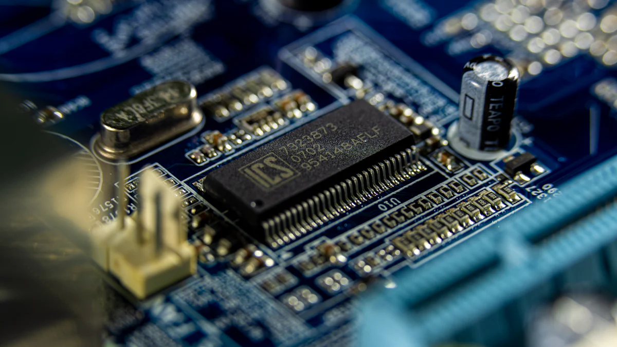
Minimizing Noise
Short and wide traces for high-current paths
High-current paths on the PCB should use short and wide traces. This reduces resistance and minimizes voltage drops, ensuring efficient power delivery. Wider traces also help lower electromagnetic interference (EMI), which can disrupt sensitive components. Designers should prioritize these paths during layout to maintain signal integrity and reduce noise.
Proper placement of decoupling capacitors
Decoupling capacitors must be placed as close as possible to the power pins of the LTC3787EUFD#PBF. This placement minimizes parasitic inductance and ensures effective filtering of high-frequency noise. For optimal results, use ceramic capacitors with low ESR and position them directly between the power and ground planes.
Ensuring Thermal Efficiency
Thermal vias and copper planes for heat dissipation
Thermal management is critical for the LTC3787EUFD#PBF, especially in high-power applications. Designers should use thermal vias to connect the top and bottom copper layers, allowing heat to spread evenly. Large copper planes under heat-generating components, such as MOSFETs and inductors, further enhance heat dissipation.
Optimizing airflow around MOSFETs and inductors
Proper airflow around heat-sensitive components prevents overheating. Designers should avoid placing MOSFETs and inductors in enclosed spaces. Instead, position them in areas with adequate ventilation or near heat sinks. This ensures consistent thermal performance and prolongs component lifespan.
Grounding Techniques
Solid ground plane implementation
A solid ground plane improves electrical performance and reduces noise. It provides a low-impedance path for return currents, enhancing stability. For the LTC3787EUFD#PBF, a dedicated ground plane also simplifies layout and minimizes the risk of signal interference.
Avoiding ground loops
Ground loops can cause unwanted noise and instability. To prevent this, designers should connect all ground points to a single reference plane. This approach eliminates potential differences between ground connections, ensuring reliable operation.
Fine-Tuning and Testing the LTC3787EUFD#PBF
Adjusting Feedback Loops
Setting correct feedback resistor values
Feedback resistors play a critical role in determining the output voltage of the LTC3787EUFD#PBF. Engineers must calculate the resistor values based on the desired output voltage using the formula provided in the datasheet. Incorrect values can lead to unstable operation or incorrect voltage levels. Precision in selecting these resistors ensures the converter delivers the intended performance.
Ensuring loop stability with compensation components
Compensation components, such as capacitors and resistors, stabilize the feedback loop. Proper selection of these components prevents oscillations and ensures smooth operation under varying load conditions. Designers should evaluate the system’s phase margin and gain margin to confirm stability. Simulation tools can assist in fine-tuning these parameters for optimal results.
Setting Switching Frequency
Balancing efficiency and component size
The switching frequency directly impacts efficiency and component size. Lower frequencies improve efficiency but require larger inductors and capacitors. Higher frequencies reduce component size but increase switching losses. The LTC3787EUFD#PBF offers an adjustable frequency range from 105kHz to 760kHz, allowing designers to strike the right balance for their application.
Programming frequency using the RT pin
The RT pin enables precise control of the switching frequency. Designers can program the frequency by connecting a resistor to this pin. The proprietary constant on-time control architecture of the LTC3787EUFD#PBF ensures fast transient response, making it suitable for applications requiring quick adjustments to load changes. Dual independent boost outputs further enhance flexibility in multi-output designs.
Testing for Stability
Load transient tests
Load transient testing evaluates the converter’s response to sudden changes in load. Engineers should monitor the output voltage during these tests to ensure it remains within acceptable limits. A fast recovery time indicates a well-tuned system, while excessive overshoot or undershoot may require adjustments to compensation components.
Measuring output ripple and noise
Output ripple and noise measurements verify the quality of the power delivered by the LTC3787EUFD#PBF. Using an oscilloscope, designers can measure these parameters under various load conditions. Low ripple and noise levels indicate effective filtering and stable operation. If measurements exceed acceptable thresholds, adjustments to capacitors or layout may be necessary.
Common Pitfalls and Troubleshooting with the LTC3787EUFD#PBF
Frequent Mistakes
Incorrect component values
Using incorrect component values often leads to performance issues. For example, selecting an inductor with insufficient current rating can cause saturation, resulting in reduced efficiency or overheating. Similarly, choosing capacitors with low voltage ratings may lead to premature failure. Engineers should always calculate and verify component values based on the design requirements. Referring to the datasheet ensures compatibility and optimal performance.
Poor PCB layout causing noise issues
Improper PCB layout can introduce noise and instability. Long, narrow traces in high-current paths increase resistance and electromagnetic interference (EMI). Placing decoupling capacitors far from the LTC3787EUFD#PBF reduces their effectiveness in filtering noise. Designers should follow best practices, such as using short, wide traces and positioning components close to the IC, to minimize these issues.
Troubleshooting Tips
Diagnosing startup issues
Startup problems can occur due to incorrect soft-start capacitor values or insufficient input voltage. Engineers should first check the input voltage to ensure it meets the minimum requirement specified in the datasheet. Verifying the soft-start capacitor value helps ensure the converter ramps up smoothly. If the issue persists, inspecting the feedback loop and compensation components may reveal further insights.
Resolving thermal problems
Thermal issues often arise from inadequate heat dissipation. High RDS(on) MOSFETs or insufficient copper planes can exacerbate overheating. Designers should inspect the PCB layout for proper thermal vias and ensure adequate copper area under heat-generating components. Improving airflow around the LTC3787EUFD#PBF and adding heat sinks can further enhance thermal performance. Monitoring the system under load conditions helps identify and address potential hotspots.
Tip: Always test the system under real-world conditions to uncover hidden issues before deployment.
Designing with the LTC3787EUFD#PBF becomes more effective when engineers focus on critical aspects like component selection, PCB layout, fine-tuning, and troubleshooting. Choosing the right inductors, capacitors, and MOSFETs ensures efficiency and stability. Proper PCB layout minimizes noise and enhances thermal performance, while fine-tuning feedback loops and switching frequency optimizes system behavior. Testing under real-world conditions confirms reliability.
For further learning, engineers can explore resources such as:
-
LTC3786IMSE#PBF – Analog Devices Inc.
Applying these practices and leveraging available resources will help create efficient, stable, and reliable designs.
FAQ
What is the recommended input voltage range for the LTC3787EUFD#PBF?
The LTC3787EUFD#PBF operates efficiently with input voltages as low as 4.5V. However, the exact range depends on the desired output voltage and system requirements. Designers should consult the datasheet for specific input-output voltage relationships.
How can engineers minimize output voltage ripple?
Using low ESR capacitors for output filtering significantly reduces voltage ripple. Placing these capacitors close to the load and ensuring proper PCB layout further enhances ripple suppression. Designers should also verify capacitor values during testing.
Can the LTC3787EUFD#PBF handle high-current applications?
Yes, the LTC3787EUFD#PBF supports high-current applications when paired with appropriately rated inductors and MOSFETs. Ensuring proper thermal management, such as using copper planes and thermal vias, is essential for reliable operation under heavy loads.
How do you program the switching frequency?
The switching frequency is set by connecting a resistor to the RT pin. The resistor value determines the frequency within the range of 105kHz to 760kHz. Designers should balance efficiency and component size when selecting the frequency.
What are common signs of instability in a boost converter?
Instability often manifests as excessive output voltage ripple, oscillations, or slow transient response. Engineers should check feedback loop compensation, verify component values, and ensure proper PCB layout to address these issues.
See Also
Explore LPQ252-CEF for Streamlined Energy Control
Key Programming Skills for MC9S12XD256 Controllers
Three Effective Methods to Use MC9S12XET512VAG
Harnessing AD74413RBCPZ for Enhanced Process Management
Simple Networking Tips for XILINX XC7K325T-2FFG676C
