The MAX30102EFD+T stands out as a high-sensitivity pulse oximeter and heart rate monitor, designed to revolutionize health monitoring. This sensor integrates advanced optical components, including LEDs and photodetectors, to measure blood oxygen levels and heart rate with precision. Its applications span wearable health monitors, medical devices, and IoT healthcare solutions, making it a versatile choice for modern technology. With its seamless compatibility with Arduino, the MAX30102 pulse oximeter simplifies DIY projects, offering enthusiasts an accessible way to explore health tracking innovations. Keep boomingAdvantageous supply SENSOR products like this continue to empower personal health monitoring.
Key Takeaways
-
The MAX30102EFD+T sensor is a high-sensitivity device that accurately measures blood oxygen levels (SpO2) and heart rate, making it ideal for health monitoring applications.
-
To set up the sensor, essential components include the MAX30102EFD+T module, an Arduino board, jumper wires, and a USB cable for programming.
-
Integrating an OLED display can enhance your project by providing a visual output of SpO2 and heart rate data, making it more user-friendly.
-
Proper wiring and connection to the Arduino are crucial for the sensor’s functionality; follow the provided pinout diagram carefully.
-
Testing the sensor with correct finger placement is vital for obtaining accurate readings; ensure minimal movement during measurement.
-
The MAX30102EFD+T sensor is versatile, suitable for wearable devices, remote patient monitoring, and educational projects, empowering users to explore health technology.
-
Installing the necessary libraries in the Arduino IDE simplifies coding and interaction with the sensor, ensuring smooth operation.
Required Components
To set up the MAX30102EFD+T sensor for SpO2 and heart rate monitoring, specific components are necessary. These components ensure proper functionality and allow users to build a reliable system for health tracking.
Essential Components
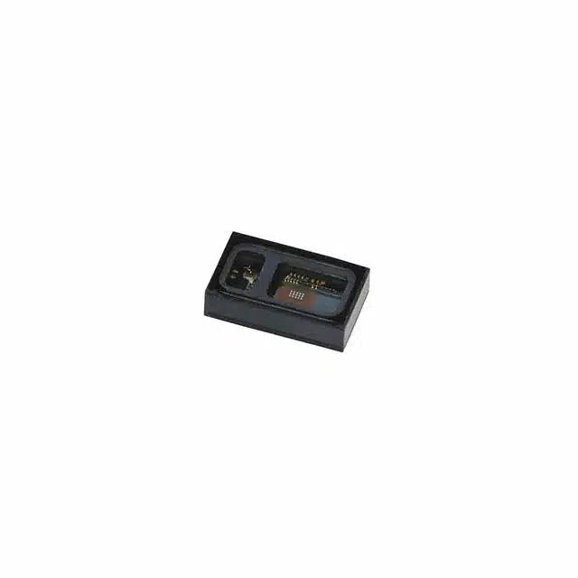
MAX30102EFD+T Sensor Module
The MAX30102EFD+T serves as the core of this project. This integrated pulse oximeter and heart-rate sensor module includes internal LEDs, photodetectors, and optimized optical elements. Its compact design and high sensitivity make it ideal for wearable devices, medical applications, and DIY projects.
Arduino Board (e.g., Uno, Nano, or Mega)
An Arduino board acts as the microcontroller for interfacing with the sensor. Popular options include the Arduino Uno, Nano, or Mega. These boards provide the necessary processing power and I2C communication protocol to read data from the sensor.
Jumper Wires and Breadboard
Jumper wires and a breadboard simplify the wiring process. They allow users to create temporary connections between the sensor, Arduino, and other components without soldering. This setup is especially useful for prototyping and testing.
USB Cable and Computer for Programming
A USB cable connects the Arduino board to a computer. The computer is used to upload the code and monitor the sensor’s output. Ensure the cable is compatible with the chosen Arduino board.
Optional Components
OLED Display for Visual Output
An OLED display enhances the project by providing a visual representation of the SpO2 and heart rate data. This feature is particularly useful for wearable applications or standalone devices.
Soldering Tools for Permanent Connections
Soldering tools are recommended for creating durable and stable connections. Once the prototype is tested, soldering ensures the circuit remains intact during extended use.
Enclosure for Wearable Applications
An enclosure protects the components and makes the device portable. For wearable applications, choose an enclosure that is lightweight and comfortable to wear.
Tip: While the essential components are sufficient for basic functionality, adding optional components can significantly improve the usability and presentation of the project.
By gathering these components, users can begin building a functional system to measure SpO2 and heart rate using the MAX30102EFD+T sensor.
Understanding the MAX30102EFD+T Sensor
Overview of the Sensor
Key Features and Specifications
The MAX30102EFD+T sensor is a compact and advanced module designed for pulse oximetry and heart rate monitoring. It integrates red and infrared LEDs, a photodetector, and optimized optical elements to deliver precise measurements. The module also includes low-noise electronics and ambient light rejection, ensuring reliable performance even in dynamic environments. Its small size and high sensitivity make it ideal for wearable devices and portable health monitoring systems.
Key specifications of the MAX30102EFD+T include:
-
Integrated red and infrared LEDs for accurate SpO2 and heart rate detection.
-
Photodetectors with enhanced sensitivity to detect reflected light intensity.
-
Low-noise electronics to minimize interference and improve signal quality.
-
Compatibility with I2C communication for seamless integration with microcontrollers like Arduino.
-
Compact design suitable for wearable and mobile applications.
This sensor provides a complete solution for developers, simplifying the process of creating health monitoring devices.
Applications in Health Monitoring and IoT
The MAX30102EFD+T sensor finds applications in various fields, particularly in health monitoring and IoT-based solutions. It plays a crucial role in:
-
Wearable Health Devices: Used in fitness trackers and smartwatches to monitor blood oxygen levels and heart rate during daily activities or workouts.
-
Medical Diagnostics: Integrated into portable medical devices for real-time SpO2 and heart rate monitoring, aiding in patient care and diagnostics.
-
IoT Healthcare Systems: Incorporated into smart health platforms for continuous monitoring and data analysis in connected healthcare ecosystems.
-
Fitness and Sports: Utilized in performance tracking devices to assess cardiovascular activity and optimize training routines.
The versatility of the MAX30102EFD+T sensor makes it a valuable component in modern health technology.
Working Principle
Explanation of Photoplethysmography (PPG)
The MAX30102 PPG heart rate sensor operates on the principle of Photoplethysmography (PPG). This non-invasive optical technique measures changes in blood volume within the microvascular bed of tissue. The sensor emits light from its red and infrared LEDs, which penetrates the skin and interacts with the blood vessels beneath.
As blood flows through the vessels, it absorbs light at specific wavelengths. The photodetector in the sensor captures the reflected light, and the variations in light intensity correspond to the pulsatile nature of blood flow. These variations form the basis for calculating heart rate and blood oxygen saturation (SpO2).
PPG technology is widely used in wearable devices due to its simplicity and effectiveness in monitoring cardiovascular health.
How the Sensor Measures SpO2 and Heart Rate
The MAX30102EFD+T sensor measures SpO2 and heart rate by analyzing the reflected light signals. Here’s how it works:
-
SpO2 Measurement: The sensor uses the red and infrared LEDs to determine the ratio of oxygenated to deoxygenated hemoglobin in the blood. Oxygenated hemoglobin absorbs more infrared light, while deoxygenated hemoglobin absorbs more red light. By comparing the intensity of reflected light at these wavelengths, the sensor calculates the blood oxygen level (SpO2).
-
Heart Rate Detection: The sensor detects the periodic changes in light absorption caused by the pulsatile flow of blood. These changes correspond to the heartbeat, allowing the sensor to calculate the heart rate.
The MAX30102 pulse oximeter processes the raw data using its internal components and sends the results to a microcontroller for further analysis or display. This efficient system ensures accurate and real-time monitoring of vital health parameters.
Wiring and Circuit Setup
Setting up the MAX30102EFD+T sensor requires careful attention to wiring and circuit connections. This section provides a detailed guide to ensure proper integration with an Arduino board.
Connection Diagram
Pinout of the MAX30102EFD+T Sensor
The MAX30102EFD+T sensor features a straightforward pin configuration, making it easy to connect to a microcontroller. The key pins include:
-
VIN: Supplies power to the sensor. Connect this pin to the 3.3V or 5V output of the Arduino, depending on the sensor module specifications.
-
GND: Serves as the ground connection. Link this pin to the GND pin on the Arduino.
-
SCL: Functions as the clock line for I2C communication. Attach this pin to the Arduino’s SCL pin (A5 on Uno, D21 on Mega).
-
SDA: Acts as the data line for I2C communication. Connect this pin to the Arduino’s SDA pin (A4 on Uno, D20 on Mega).
Note: Ensure the sensor module’s voltage requirements match the Arduino’s output to avoid damage.
Wiring the Sensor to the Arduino
To establish a reliable connection between the MAX30102EFD+T sensor and the Arduino, follow these steps:
-
Use jumper wires to connect the VIN pin of the sensor to the Arduino’s 3.3V or 5V pin.
-
Link the GND pin of the sensor to the Arduino’s GND pin.
-
Attach the SCL pin of the sensor to the Arduino’s SCL pin.
-
Connect the SDA pin of the sensor to the Arduino’s SDA pin.
This basic wiring setup enables communication between the sensor and the Arduino through the I2C protocol.
Step-by-Step Instructions
Connecting the Sensor to the Arduino
-
Place the MAX30102EFD+T sensor module on a breadboard for stability during the wiring process.
-
Use jumper wires to connect the sensor’s pins to the corresponding Arduino pins as described in the connection diagram.
-
Double-check all connections to ensure accuracy and prevent potential issues during operation.
-
Power the Arduino using a USB cable connected to a computer. This step also prepares the board for programming.
Tip: Keep the wiring neat and organized to simplify troubleshooting and testing.
Adding an OLED Display (Optional)
For users who wish to display SpO2 and heart rate data visually, integrating an OLED display enhances the project. Follow these steps to add an OLED display:
-
Connect the OLED display’s VCC pin to the Arduino’s 3.3V or 5V pin, depending on the display’s voltage requirements.
-
Link the GND pin of the OLED display to the Arduino’s GND pin.
-
Attach the SCL pin of the OLED display to the Arduino’s SCL pin.
-
Connect the SDA pin of the OLED display to the Arduino’s SDA pin.
This setup allows the Arduino to communicate with both the MAX30102EFD+T sensor and the OLED display using the I2C protocol. Ensure the I2C addresses of the sensor and display do not conflict.
Note: Some OLED displays may require additional libraries for proper functionality. Refer to the display’s documentation for details.
By following these steps, users can successfully wire the MAX30102EFD+T sensor and optionally integrate an OLED display for enhanced functionality.
Installing Libraries
To use the MAX30102EFD+T sensor effectively, installing the correct libraries is essential. These libraries provide the necessary tools to communicate with the sensor and display data accurately. This section outlines the required libraries and guides users through the installation process.
Required Libraries
SparkFun MAX3010x Library
The SparkFun MAX3010x library simplifies the interaction between the MAX30102EFD+T sensor and the Arduino. It includes pre-written functions for initializing the sensor, reading data, and processing SpO2 and heart rate measurements. This library eliminates the need to write complex code from scratch, making it an indispensable resource for developers.
Adafruit GFX and SSD1306 Libraries (for OLED Display)
For projects that include an OLED display, the Adafruit GFX and SSD1306 libraries are necessary. The Adafruit GFX library provides graphics functions, such as drawing shapes and text, while the SSD1306 library enables communication with OLED displays. Together, these libraries allow users to create a visually appealing interface for displaying SpO2 and heart rate data.
Installation Steps
How to Install Libraries Using the Arduino IDE
Installing libraries in the Arduino IDE is a straightforward process. Follow these steps to add the required libraries:
-
Open the Arduino IDE on your computer.
-
Navigate to the Sketch menu and select Include Library > Manage Libraries.
-
In the Library Manager window, type “SparkFun MAX3010x” in the search bar.
-
Locate the SparkFun MAX3010x library in the search results and click Install.
-
Repeat the process for the Adafruit GFX and Adafruit SSD1306 libraries by searching for their names and clicking Install.
Tip: Ensure your Arduino IDE is updated to the latest version to avoid compatibility issues with the libraries.
Verifying Successful Installation
After installing the libraries, verify their successful integration into the Arduino IDE:
-
Go to File > Examples in the Arduino IDE.
-
Look for example sketches under the SparkFun MAX3010x, Adafruit GFX, and Adafruit SSD1306 sections.
-
Open one of the example sketches and click the Verify button (checkmark icon) to compile the code.
-
If the compilation completes without errors, the libraries have been installed correctly.
Note: If errors occur during compilation, double-check the library names and ensure they were installed from the official sources.
By completing these steps, users can prepare their Arduino environment for working with the MAX30102EFD+T sensor and optional OLED display. Proper library installation ensures smooth communication between the hardware and software components.
Writing and Uploading Arduino Code
Example Code for SpO2 and Heart Rate
Explanation of the Code Structure
The code for the MAX30102 sensor follows a structured approach to ensure accurate readings of SpO2 and heart rate. The program begins by including the necessary libraries, such as the SparkFun MAX3010x library, which simplifies communication with the sensor. These libraries provide pre-written functions to initialize the sensor and process the data it collects.
The setup function initializes the sensor and establishes communication between the Arduino and the MAX30102 module. It also configures the serial monitor to display the output. The loop function continuously reads data from the sensor, processes it, and displays the calculated SpO2 and heart rate values. This structure ensures that the program runs efficiently and provides real-time results.
Tip: Always verify that the libraries are correctly installed before uploading the code to avoid compilation errors.
Key Functions for Reading Sensor Data
The code uses specific functions to interact with the MAX30102 sensor and retrieve data. These functions include:
-
begin(): Initializes the sensor and checks if it is connected properly.
-
check(): Reads raw data from the sensor and processes it for further calculations.
-
getHeartRate(): Calculates the heart rate by analyzing the rhythm of reflected red and infrared light.
-
getSpO2(): Determines the SpO2 level by comparing the absorption of red and infrared light.
These functions work together to ensure accurate measurements of SpO2 and heart rate. The processed data is then displayed on the serial monitor or an optional OLED screen.
Note: The MAX30102 PPG heart rate sensor relies on precise timing and proper placement to deliver reliable results. Ensure the sensor is securely connected and positioned correctly during testing.
Uploading the Code
Steps to Upload the Code to the Arduino
Uploading the code to the Arduino involves a straightforward process. Follow these steps to ensure a successful upload:
-
Open the Arduino IDE on your computer.
-
Connect the Arduino board to the computer using a USB cable.
-
Copy the example code for the MAX30102 sensor into the Arduino IDE.
-
Select the correct board and port under the Tools menu. For example, choose “Arduino Uno” if you are using an Uno board.
-
Click the Verify button (checkmark icon) to compile the code. This step checks for errors in the code.
-
Once the compilation is successful, click the Upload button (arrow icon) to transfer the code to the Arduino.
The Arduino will begin running the uploaded code immediately after the upload process completes.
Tip: Ensure the USB cable is securely connected to avoid interruptions during the upload process.
Verifying the Code is Running Correctly
After uploading the code, verify that the Arduino and sensor are functioning as expected:
-
Open the Serial Monitor in the Arduino IDE by clicking the magnifying glass icon in the top-right corner.
-
Set the baud rate in the Serial Monitor to match the one specified in the code (e.g., 9600).
-
Observe the output on the Serial Monitor. The SpO2 and heart rate values should appear in real time.
-
If an OLED display is connected, check that the data is also displayed on the screen.
If the sensor does not produce readings or the values seem inaccurate, double-check the wiring and ensure the sensor is properly positioned. Re-upload the code if necessary.
Note: Proper finger placement on the sensor is crucial for accurate readings. Place the fingertip gently on the sensor without applying excessive pressure.
By following these steps, users can successfully upload and run the code for the MAX30102 sensor. This process enables real-time monitoring of SpO2 and heart rate, making it a valuable tool for health tracking projects.
Displaying Results
Using the Serial Monitor
How to view SpO2 and heart rate data in the Arduino IDE
The Serial Monitor in the Arduino IDE provides a straightforward way to view the SpO2 and heart rate data collected by the MAX30102 sensor. This tool allows users to observe real-time readings directly on their computer screen.
To access the data, follow these steps:
-
Open the Arduino IDE after uploading the code to the Arduino board.
-
Click on the Serial Monitor icon located in the top-right corner of the IDE. Alternatively, navigate to Tools > Serial Monitor.
-
Set the baud rate in the Serial Monitor to match the one specified in the code (e.g., 9600). This ensures proper communication between the Arduino and the computer.
-
Observe the output displayed in the Serial Monitor. The SpO2 and heart rate values will appear as numerical data, updating continuously.
Tip: Ensure the sensor is properly connected and the finger placement is correct to obtain accurate readings. Avoid excessive movement during measurement to maintain stable data.
The Serial Monitor serves as an essential debugging and testing tool. It allows users to verify that the sensor is functioning correctly and provides a simple way to monitor health parameters without additional hardware.
Using an OLED Display
Example code for displaying results on an OLED
An OLED display enhances the project by providing a visual representation of the SpO2 and heart rate data. This feature is particularly useful for wearable devices or standalone health monitors. Below is an example code snippet for displaying the results on an OLED screen:
#include <Wire.h>
#include <Adafruit_GFX.h>
#include <Adafruit_SSD1306.h>
#include <SparkFun_MAX3010x.h>

#define SCREEN_WIDTH 128
#define SCREEN_HEIGHT 64
Adafruit_SSD1306 display(SCREEN_WIDTH, SCREEN_HEIGHT, &Wire, -1);

MAX30105 particleSensor;

void setup() {
  Serial.begin(9600);
  if (!display.begin(SSD1306_I2C_ADDRESS, 0x3C)) {
    Serial.println("OLED initialization failed");
    while (true);
  }
  display.clearDisplay();
  display.setTextSize(1);
  display.setTextColor(SSD1306_WHITE);

  if (!particleSensor.begin()) {
    Serial.println("MAX30102 not detected");
    while (true);
  }
}

void loop() {
  int heartRate = particleSensor.getHeartRate();
  int spO2 = particleSensor.getSpO2();

  display.clearDisplay();
  display.setCursor(0, 0);
  display.print("Heart Rate: ");
  display.print(heartRate);
  display.println(" BPM");
  display.print("SpO2: ");
  display.print(spO2);
  display.println(" %");
  display.display();

  delay(1000);
}
This code initializes the OLED display and the MAX30102 sensor. It retrieves the heart rate and SpO2 data, then displays the values on the screen in a readable format.
Note: Ensure the Adafruit GFX and SSD1306 libraries are installed in the Arduino IDE before uploading the code.
Adjusting the display for better readability
To improve the readability of the OLED display, consider the following adjustments:
-
Font Size: Increase the text size using the
setTextSize()function. For example, changingsetTextSize(1)tosetTextSize(2)will make the text larger and easier to read. -
Contrast: Modify the brightness of the OLED display to suit different lighting conditions. Refer to the display’s documentation for instructions on adjusting contrast settings.
-
Layout: Organize the data on the screen for clarity. Use separate lines for each parameter and align the text properly. For instance, place “Heart Rate” and “SpO2” on different rows with adequate spacing.
-
Icons and Graphics: Add simple icons or graphics to represent heart rate and SpO2 visually. The Adafruit GFX library provides functions for drawing shapes and symbols.
Tip: Test the display under various conditions to ensure the data remains visible and legible. This step is crucial for wearable applications where users may need to glance at the screen quickly.
By integrating an OLED display, users can create a more interactive and user-friendly health monitoring system. The visual output not only enhances the project’s functionality but also makes it more appealing and practical for everyday use.
Testing and Troubleshooting
Testing the Setup
How to Test the Sensor for Accurate Readings
Testing the MAX30102EFD+T sensor ensures that it provides reliable and accurate data. Follow these steps to verify the sensor’s performance:
-
Power the Setup: Connect the Arduino to a computer using a USB cable. Ensure the wiring between the sensor and the Arduino matches the connection diagram.
-
Open the Serial Monitor: Launch the Arduino IDE and open the Serial Monitor. Set the baud rate to match the one specified in the code (e.g., 9600).
-
Place a Finger on the Sensor: Gently place a fingertip on the sensor module. Ensure the finger covers the sensor completely without applying excessive pressure.
-
Observe the Output: Monitor the SpO2 and heart rate values displayed on the Serial Monitor or OLED screen. The readings should update in real time.
Tip: Perform the test in a stable environment with minimal movement. Excessive motion or poor lighting conditions can interfere with the sensor readings.
Accurate testing confirms that the sensor operates as intended and provides dependable health data.
Tips for Ensuring Proper Finger Placement
Proper finger placement plays a critical role in obtaining accurate results. Consider the following tips:
-
Position the Finger Correctly: Place the fingertip flat on the sensor, ensuring full coverage of the LEDs and photodetector.
-
Avoid Excessive Pressure: Pressing too hard can restrict blood flow, leading to inaccurate readings. Maintain light but firm contact.
-
Minimize Movement: Keep the hand steady during measurement. Movement can disrupt the light signals and affect the accuracy of the data.
-
Clean the Sensor Surface: Wipe the sensor with a soft cloth to remove dirt or smudges. A clean surface improves light transmission and reflection.
Note: Testing multiple fingers may help identify the one that provides the most stable readings. Some individuals may achieve better results with specific fingers.
Common Issues and Fixes
Sensor Not Detected by Arduino
If the Arduino fails to detect the MAX30102EFD+T sensor, follow these troubleshooting steps:
-
Check the Wiring: Verify that all connections between the sensor and Arduino are secure and match the pinout diagram. Loose or incorrect wiring often causes detection issues.
-
Inspect the Voltage Supply: Ensure the sensor receives the correct voltage (3.3V or 5V) as specified in its datasheet. Incorrect voltage can damage the sensor or prevent it from functioning.
-
Confirm I2C Communication: Use an I2C scanner sketch to check if the Arduino detects the sensor’s I2C address. If the address does not appear, recheck the SDA and SCL connections.
Tip: Replace jumper wires if they appear damaged or worn. Faulty wires can interrupt communication between the sensor and Arduino.
Inaccurate or Unstable Readings
Unstable or incorrect readings can result from several factors. Address these issues with the following solutions:
-
Ensure Proper Finger Placement: Refer to the tips mentioned earlier for correct finger positioning. Improper placement often leads to fluctuating data.
-
Reduce Ambient Light Interference: Perform measurements in a dimly lit environment. Bright ambient light can interfere with the sensor’s ability to detect reflected light.
-
Stabilize the Sensor: Secure the sensor module on a flat surface or within an enclosure. Movement or vibrations can disrupt the readings.
Note: Allow the sensor a few seconds to stabilize after placing the finger. Initial readings may fluctuate before settling.
Troubleshooting Wiring and Code Errors
Wiring and code errors are common obstacles when working with the MAX30102EFD+T sensor. Resolve these issues with the following steps:
-
Double-Check Connections: Compare the wiring setup with the connection diagram. Ensure all pins are connected to their corresponding Arduino pins.
-
Verify the Code: Review the uploaded code for errors. Ensure the correct libraries are included and initialized properly.
-
Test with Example Code: Use example sketches from the SparkFun MAX3010x library to confirm the sensor’s functionality. These pre-written codes eliminate potential errors in custom scripts.
Tip: Restart the Arduino and sensor after making changes to the wiring or code. This step ensures the updates take effect.
By addressing these common issues, users can optimize the performance of the MAX30102EFD+T sensor and achieve accurate, stable results.
Applications and Use Cases
Health Monitoring Devices
Wearable Fitness Trackers
Wearable fitness trackers have become essential tools for individuals aiming to monitor their health. The MAX30102EFD+T sensor plays a pivotal role in these devices by providing accurate measurements of heart rate and blood oxygen saturation. Fitness enthusiasts rely on these trackers to assess their cardiovascular performance during workouts. The sensor’s compact design and high sensitivity make it ideal for integration into wristbands and smartwatches. By continuously tracking heart rate and blood oxygen levels, wearable fitness trackers empower users to optimize their exercise routines and maintain a healthy lifestyle.
Remote Patient Monitoring Systems
Remote patient monitoring systems leverage the capabilities of the MAX30102 pulse oximeter to deliver real-time health data. These systems enable healthcare providers to monitor patients’ vital signs, such as SpO2 and heart rate, from a distance. The MAX30102EFD+T sensor ensures precise readings, making it a reliable choice for medical applications. Patients with chronic conditions benefit from these systems as they reduce the need for frequent hospital visits. The sensor’s ability to measure blood oxygen saturation and heart rate accurately enhances the effectiveness of remote healthcare solutions.
IoT and DIY Projects
Smart Home Health Monitoring
The MAX30102EFD+T sensor has found its place in smart home health monitoring systems. These systems integrate the sensor with Arduino to create devices that track vital signs like heart rate and blood oxygen levels. The data collected by the sensor can be transmitted to smartphones or cloud platforms for analysis. This setup allows users to monitor their health conveniently at home. The sensor’s advanced features, such as low noise and high sensitivity, ensure reliable performance in dynamic environments. Smart home health monitoring systems represent a significant step toward personalized healthcare.
Educational Projects for Learning Electronics
The MAX30102 PPG heart rate sensor serves as an excellent tool for educational projects. Students and hobbyists use this sensor to learn about electronics, programming, and biomedical engineering. By interfacing the sensor with Arduino, learners can explore how to measure SpO2 and heart rate. These projects provide hands-on experience in working with sensors, processing data, and displaying results. The MAX30102EFD+T sensor’s straightforward integration and versatility make it a popular choice for educational purposes. Aspiring engineers and developers gain valuable skills while creating functional health monitoring devices.
The MAX30102EFD+T sensor offers a straightforward tutorial for setting up a reliable system to measure heart rate and blood oxygen levels. Its integration into wearable devices and IoT applications highlights its versatility in real-time health monitoring. By following the steps outlined, users can explore its potential in creating innovative solutions for personal health tracking. The sensor’s low power consumption and advanced features make it an ideal choice for DIY projects, enabling enthusiasts to develop efficient and compact health monitor systems with ease.
FAQ
What is the MAX30102EFD+T sensor used for?
The MAX30102EFD+T sensor measures blood oxygen levels (SpO2) and heart rate. It is commonly used in wearable health devices, medical equipment, and IoT healthcare systems. Its compact design and high sensitivity make it ideal for fitness trackers, remote patient monitoring, and educational projects.
How does the MAX30102EFD+T sensor work?
The sensor uses Photoplethysmography (PPG) technology. It emits red and infrared light, which penetrates the skin and interacts with blood vessels. The photodetector captures the reflected light, and the sensor processes the data to calculate SpO2 and heart rate.
Can the MAX30102EFD+T sensor be used with Arduino?
Yes, the MAX30102EFD+T sensor integrates seamlessly with Arduino boards. It uses the I2C communication protocol, which simplifies wiring and programming. Libraries like the SparkFun MAX3010x library provide pre-written functions to interact with the sensor.
What components are required to set up the MAX30102EFD+T sensor?
To set up the sensor, users need the following essential components:
-
MAX30102EFD+T sensor module
-
Arduino board (e.g., Uno, Nano, or Mega)
-
Jumper wires and a breadboard
-
USB cable and a computer for programming
Optional components include an OLED display for visual output, soldering tools for permanent connections, and an enclosure for wearable applications.
How do you install the required libraries for the MAX30102EFD+T sensor?
To install the libraries, open the Arduino IDE and navigate to Sketch > Include Library > Manage Libraries. Search for “SparkFun MAX3010x” and click “Install.” For OLED displays, search for and install the “Adafruit GFX” and “Adafruit SSD1306” libraries. Verify the installation by compiling example sketches provided by the libraries.
What are the common issues when using the MAX30102EFD+T sensor?
Common issues include:
-
Sensor not detected by the Arduino: Check wiring and ensure proper voltage supply.
-
Inaccurate readings: Ensure correct finger placement and reduce ambient light interference.
-
Code errors: Verify the code and confirm that all required libraries are installed.
How can users view the sensor’s output?
Users can view the output through the Arduino IDE’s Serial Monitor or an OLED display. The Serial Monitor shows real-time SpO2 and heart rate data as numerical values. An OLED display provides a visual representation, making it suitable for wearable or standalone devices.
Is the MAX30102EFD+T sensor suitable for wearable applications?
Yes, the sensor’s compact size and low power consumption make it ideal for wearable devices. It integrates easily into fitness trackers, smartwatches, and portable health monitors. Adding an enclosure enhances its portability and durability.
What is the importance of proper finger placement on the sensor?
Proper finger placement ensures accurate readings. Users should place their fingertip flat on the sensor, covering the LEDs and photodetector. Excessive pressure or movement can disrupt the measurements. Testing multiple fingers may help identify the one that provides the most stable results.
Can the MAX30102EFD+T sensor be used for educational purposes?
Yes, the sensor is an excellent tool for learning electronics and programming. Students and hobbyists can use it to explore biomedical engineering concepts. By interfacing the sensor with Arduino, learners gain hands-on experience in building functional health monitoring systems.
See Also
Simple Guide to Integrating SN74LVC4245APW Sensors
M30280FAHP: A Trustworthy Option for Medical Applications
Three Effective Methods for MC9S12XET512VAG Integration
Integrating AEAT-8800-Q24 to Boost Robotics Efficiency
SPC56 Microcontrollers: Simple Solutions for Engine Control