
The MFRC522 RFID reader Zambia users rely on is an essential tool for Arduino projects due to its affordability and reliability. This versatile module supports multiple communication interfaces, including SPI, I2C, and UART, providing flexibility for various applications. Operating at 13.56 MHz, a common frequency for RFID systems, the MFRC522 can read from and write to RFID tags, making it ideal for inventory management and access control. In Zambia, the MFRC522 ESP32 attendance system in Zambia is a popular application, helping to improve efficiency in educational environments.
Key Takeaways
-
The MFRC522 RFID reader works well with Arduino boards and supports easy wiring using SPI pins and 3.3V power.
-
Using the MFRC522 library helps read and write data on MIFARE tags for applications like attendance and access control.
-
Double-check wiring and use quality components to avoid common issues like detection failures or damage to the module.
-
Test your setup with example codes and multiple RFID tags to ensure reliable operation and troubleshoot problems.
-
The MFRC522 RFID reader enables creative projects in Zambia, such as inventory management, student attendance, and healthcare access control.
Components
MFRC522 RFID Reader
The MFRC522 RFID reader serves as the heart of many Arduino projects. This module operates at 13.56 MHz and supports various MIFARE cards, making it suitable for diverse applications. In Zambia, users often choose the MFRC522 for its affordability and reliability. It connects easily to Arduino boards via the SPI interface, allowing for seamless communication.
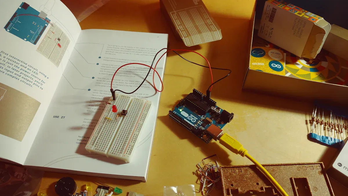
Arduino Board
An Arduino board is essential for any project involving the MFRC522 RFID reader. The Arduino Uno is a popular choice due to its compatibility and ease of use. Other boards, such as the Arduino Mega or Nano, also work well, provided they support SPI communication. This flexibility allows users in Zambia to select a board that fits their project needs.
Jumper Wires
Jumper wires are crucial for connecting the MFRC522 RFID reader to the Arduino board. These wires come in various lengths and types, including male-to-male, male-to-female, and female-to-female. They facilitate easy connections between components, ensuring a reliable setup.
MIFARE Tags
MIFARE tags, particularly the MIFARE Classic 1k, are commonly used with the MFRC522 RFID reader. These tags store data securely and are ideal for applications such as attendance tracking and access control. In Zambia, educational institutions often utilize these tags for student ID cards, enhancing security and efficiency.
|
Component |
Description/Notes |
|---|---|
|
Arduino Board |
Arduino Uno or compatible board |
|
MFRC522 Module |
RFID reader module |
|
MIFARE Tags |
Cards or key fobs for identification |
|
Jumper Wires |
For connections between components |
|
Breadboard |
For prototyping circuit |
|
LED |
Optional, for visual feedback |
|
220 ohm Resistor |
Used with LED to limit current |
These components work together to create a functional RFID system, enabling users to explore various applications in Zambia, from inventory management to access control.
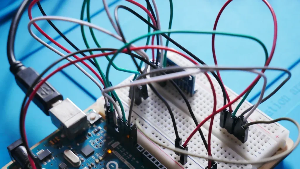
Wiring the MFRC522 RFID Reader
Connection Overview
Connecting the MFRC522 RFID reader to an Arduino board is a straightforward process. Proper wiring ensures that the reader functions correctly and communicates effectively with the Arduino. Users should follow the pin configuration closely to avoid common mistakes.
Here are the essential steps for wiring the MFRC522 RFID reader:
-
Power Supply: Connect the MFRC522’s VCC pin to the Arduino’s 3.3V pin. This voltage is crucial; supplying more than 3.3V can damage the module.
-
Ground Connection: Connect the GND pin of the MFRC522 to the GND pin on the Arduino. This establishes a common ground for both devices.
-
SPI Communication Pins: Connect the following pins for SPI communication:
-
MOSI (Master Out Slave In) to pin 11 on the Arduino.
-
MISO (Master In Slave Out) to pin 12 on the Arduino.
-
SCK (Serial Clock) to pin 13 on the Arduino.
-
-
Control Pins: Connect the RST (Reset) pin to pin 9 on the Arduino and the SDA (Slave Select) pin to pin 10. These pins can be configured to other digital pins if needed.
Tip: Always double-check connections against the pinout diagrams to prevent wiring errors. Incorrect wiring is a common cause of issues when using the MFRC522 RFID reader.
Pin Configuration
The following table outlines the recommended pin configuration for connecting the MFRC522 RFID reader to an Arduino Uno:
|
MFRC522 Pin |
Arduino Pin |
|---|---|
|
VCC |
3.3V |
|
GND |
GND |
|
RST |
9 |
|
SDA (SS) |
10 |
|
MOSI |
11 |
|
MISO |
12 |
|
SCK |
13 |
This configuration allows for seamless communication between the MFRC522 RFID reader and the Arduino. Users should ensure that the communication pins are connected correctly, as this is vital for the reader’s operation.
Common mistakes during wiring include:
-
Supplying the MFRC522 with more than 3.3V, which can damage the chip.
-
Incorrectly wiring SPI pins or connecting VCC to 5V instead of 3.3V.
-
Using faulty breadboards that can lead to connection issues.
By following these guidelines, users can successfully set up the MFRC522 RFID reader for various applications, including those relevant to the Zambian market.
Coding Examples for MFRC522
Basic Code Setup
To get started with the MFRC522 RFID reader, users must set up their Arduino environment. The first step involves installing the necessary libraries. The most commonly used library for integrating the MFRC522 RFID reader with Arduino is the ‘rfid’ library developed by Miguel Balboa. This library supports communication with MIFARE Classic cards via the SPI interface. Users can download it from GitHub and add it to their Arduino IDE.
Once the library is installed, users can initialize the MFRC522 RFID reader with the following code:
#include <SPI.h>
#include <MFRC522.h>

#define RST_PIN 9  // Reset pin
#define SS_PIN 10  // Slave Select pin

MFRC522 rfid(SS_PIN, RST_PIN);

void setup() {
  Serial.begin(9600);
  SPI.begin();
  rfid.PCD_Init();
  Serial.println("Place your RFID tag near the reader...");
}

void loop() {
  if (!rfid.PICC_IsNewCardPresent() || !rfid.PICC_ReadCardSerial()) return;

  Serial.print("UID: ");
  for (byte i = 0; i < rfid.uid.size; i++) {
    Serial.print(rfid.uid.uidByte[i], HEX);
    Serial.print(" ");
  }
  Serial.println();
  rfid.PICC_HaltA();
}
This code initializes the SPI bus and the MFRC522 module. It continuously checks for RFID tags, reads their UID, and prints it to the Serial Monitor. This setup is ideal for various applications, including those relevant to the Zambian market.
Reading RFID Tags
Reading RFID tags with the MFRC522 RFID reader is straightforward. After setting up the hardware and uploading the basic code, users can modify the code to read data from MIFARE tags. Here are the steps to read data:
-
Connect the MFRC522 RFID reader to the Arduino using the specified pins.
-
Use the example sketch ‘DumpInfo’ from the library to read all data from the MIFARE tag.
-
Upload the example code to the Arduino and open the Serial Monitor to view the UID and other card data.
Users can customize the code to compare the UID against a predefined authorized UID to grant or deny access. This feature is particularly useful in educational institutions in Zambia, where RFID tags can serve as student ID cards.
Writing to RFID Tags
Writing data to MIFARE tags using the MFRC522 RFID reader involves several steps. Users can follow this process:
-
Connect the MFRC522 RFID reader to the Arduino using SPI protocol.
-
Install the MFRC522 Arduino library by Miguel Balboa.
-
Test the setup by uploading the DumpInfo example sketch to verify communication with the RFID reader and tag.
-
Prepare the Arduino sketch to write data. Initialize SPI and MFRC522, set the default authentication key, and wait for a new RFID card.
When a card is detected, users can use the writeBlock() function to write data arrays to specific writable blocks. The function authenticates with the sector trailer block before writing. After writing, users can read back data from the same blocks to verify the operation.
Tip: Monitor the Serial Monitor at 115200 baud to see status messages, data written, and data read from the tag. This feedback helps users ensure that their RFID systems function correctly.
By following these coding examples, users can effectively utilize the MFRC522 RFID reader in various applications, enhancing efficiency and security in Zambian contexts.
Troubleshooting Tips
Common Issues
Users often encounter several common issues when working with the MFRC522 RFID reader. Here are some frequently reported problems:
-
Inconsistent Detection: Users may experience unreliable detection of RFID tags. This issue often arises with cheaper variants of the MFRC522, leading to random detection failures despite correct wiring.
-
No Error Messages: Sometimes, the reader initializes but fails to detect tags. Users might see no errors in the Serial Monitor, indicating potential hardware or signal issues.
-
Wiring Problems: Incorrect wiring can lead to detection failures. For instance, using a single 6-conductor wire for power and communication works well, while splitting the wiring can cause issues.
-
Quality of Components: Poor quality components, especially inductors in the antenna circuit, can affect detection reliability. Users may need to replace these components to improve performance.
Debugging Techniques
To resolve issues with the MFRC522 RFID reader, users can follow these effective debugging techniques:
-
Verify Connections: Carefully check all hardware connections. This step is crucial, especially on boards like NodeMCU, where pins are closely spaced.
-
Check SS Pin: Ensure the Slave Select (SS) pin defined in the code matches the physical wiring. Common SS pins on NodeMCU are 15 or 11, depending on the SPI instance.
-
Monitor Baud Rate: Confirm that the baud rate in the Serial Monitor matches the code’s settings, typically set at 9600.
-
Test with Multiple Tags: Use different RFID tags to rule out tag-specific issues. This approach helps identify whether the problem lies with the tags or the reader.
-
Inspect Module Quality: Assess the quality and condition of the RFID reader module. Faulty or low-quality modules may lead to failures.
-
Use Example Code: Run example sketches from the MFRC522 library, such as ReadNUID.ino, to verify basic functionality.
-
Consult Documentation: Review the official documentation and community forums for additional troubleshooting advice.
By following these tips, users can effectively troubleshoot their MFRC522 RFID reader projects, ensuring smooth operation in various applications across Zambia.
Project Ideas for Zambia
Retail Inventory Management
The retail sector in Zambia can greatly benefit from the MFRC522 RFID reader. Retailers can implement an inventory management system that tracks stock levels in real-time. By attaching MIFARE tags to products, employees can quickly scan items during stock counts. This process reduces human error and speeds up inventory checks. Retailers can also use the data collected to analyze sales trends and optimize stock levels.
Student Attendance System
Educational institutions in Zambia can enhance their attendance tracking with the MFRC522 RFID reader. Schools and universities can issue student ID cards embedded with MIFARE tags. When students enter classrooms, they can simply tap their cards on the reader. This method automates attendance logging, saving time for teachers and reducing paperwork. Additionally, it provides accurate attendance records, which can be useful for administrative purposes.
Healthcare Access Control
In healthcare settings, the MFRC522 RFID reader can improve access control to sensitive areas. Clinics and pharmacies can use RFID technology to manage access to medicine cabinets or restricted areas. By assigning MIFARE tags to authorized personnel, healthcare facilities can ensure that only designated staff can access certain medications or equipment. This system enhances security and accountability, reducing the risk of theft or misuse.
These project ideas illustrate the versatility of the MFRC522 RFID reader in various sectors across Zambia. By leveraging this technology, businesses and institutions can streamline operations, improve efficiency, and enhance security.
The MFRC522 RFID reader simplifies Arduino projects, making it accessible for beginners and experienced developers alike. Key takeaways include:
-
Use dedicated methods to read and write data on MIFARE Classic RFID cards.
-
Authenticate access to ensure secure communication.
-
Implement graceful termination of reading loops for safe operations.
This reader’s compatibility with various Arduino components fosters creativity in project development. From attendance systems to inventory management, the MFRC522 opens doors to innovative solutions. Readers should feel inspired to experiment with the project ideas discussed and unlock the full potential of RFID technology in their endeavors. 🚀
What is the MFRC522 RFID reader used for?
The MFRC522 RFID reader reads and writes data to RFID tags. It finds applications in inventory management, access control, and attendance tracking, making it versatile for various projects.
How do I connect the MFRC522 to an Arduino?
Connect the MFRC522’s VCC to the Arduino’s 3.3V, GND to GND, and the SPI pins (MOSI, MISO, SCK) to the corresponding Arduino pins. Follow the pin configuration for proper setup.
Can I use any Arduino board with the MFRC522?
Yes, most Arduino boards, including the Uno, Mega, and Nano, support the MFRC522. Ensure the board supports SPI communication for seamless integration.
What types of MIFARE tags work with the MFRC522?
The MFRC522 works with various MIFARE tags, including MIFARE Classic 1K and MIFARE Ultralight. These tags are commonly used for identification and data storage.
How can I troubleshoot detection issues with the MFRC522?
Check wiring connections, ensure the correct voltage supply, and verify the baud rate in the Serial Monitor. Testing with different RFID tags can also help identify issues.
See Also
Enhancing Process Control By Unlocking AD74413RBCPZ Features
Three Best Methods To Integrate MC9S12XET512VAG Effectively
A Detailed Look At MC9S12DJ256MFUE Specs For Vehicles
Key Programming Basics For MC9S12XD256 Microcontroller Users
Improving Automotive Performance Using NXP MC9S12XEP100 And MC9S12XS128