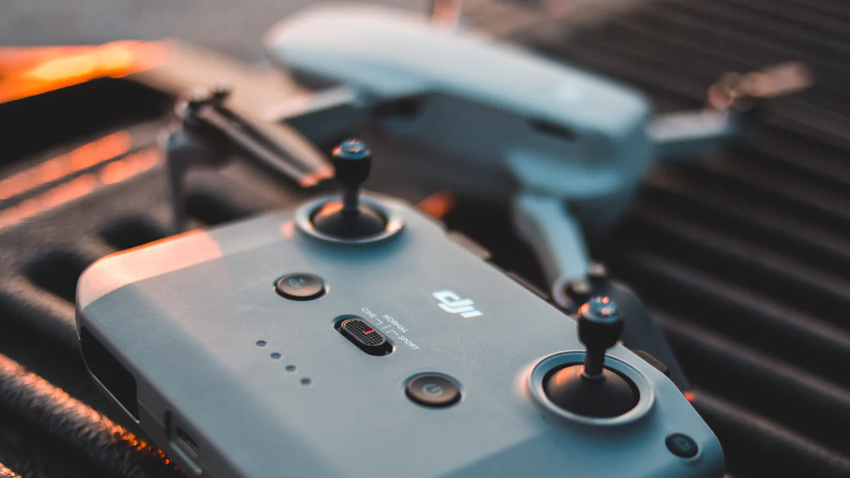
The MPU-6050 has revolutionized motion tracking in drones and quadcopters. By combining a 3-axis gyroscope and a 3-axis accelerometer, it delivers precise measurements of acceleration and angular velocity. This sensor plays a critical role in maintaining stability during flight, ensuring smooth navigation even in challenging conditions. Its onboard Digital Motion Processor (DMP) processes complex motion data, enabling accurate roll, pitch, and yaw calculations. With its ability to track motion across six degrees of freedom, the MPU-6050 has become an essential component for achieving reliable and responsive drone control.
Key Takeaways
-
The MPU-6050 combines a 3-axis gyroscope and a 3-axis accelerometer, providing precise motion tracking across six degrees of freedom, essential for stable drone navigation.
-
Utilizing the built-in Digital Motion Processor (DMP) allows for efficient data processing, reducing the load on microcontrollers and enhancing the accuracy of motion calculations.
-
Connecting the MPU-6050 to microcontrollers like Arduino is straightforward, requiring only a few simple wiring steps and the installation of necessary libraries for programming.
-
Understanding roll, pitch, and yaw is crucial for drone control; the MPU-6050 provides real-time data to help maintain stability and responsiveness during flight.
-
Implementing a PID controller with MPU-6050 data can significantly improve drone stability, allowing for quick adjustments to motor speeds based on sensor feedback.
-
Combining the MPU-6050 with other sensors, such as GPS and barometers, enhances navigation capabilities, making drones more reliable in various environments.
-
The MPU-6050 is beginner-friendly, making it an excellent choice for hobbyists and developers looking to explore motion tracking and drone technology.
Overview of the MPU-6050 Sensor
The MPU-6050 stands out as a powerful and versatile sensor for motion tracking. It combines a 3-axis accelerometer and a 3-axis gyroscope into a single compact module, making it an ideal choice for projects requiring precise motion detection. This inertial measurement unit (IMU) provides accurate data across six degrees of freedom, enabling users to measure acceleration, angular velocity, and orientation with ease. Its onboard Digital Motion Processor (DMP) simplifies complex calculations, ensuring real-time performance without overloading the main processor.
Key Features of the MPU-6050
6-axis motion tracking and real-time data processing.
The MPU-6050 excels in six-axis motion tracking, which allows it to monitor movement across three linear axes and three rotational axes. This capability is essential for applications like drones, robotics, and gaming devices. The sensor processes data in real time, ensuring smooth and responsive performance in dynamic environments.
Built-in Digital Motion Processor (DMP) for efficient calculations.
The MPU-6050 includes a built-in DMP, which handles complex motion fusion algorithms. This feature reduces the computational load on external microcontrollers, allowing them to focus on other tasks. The DMP also enhances accuracy by combining data from the accelerometer and gyroscope, delivering reliable results for motion tracking and stabilization.
I2C communication for seamless interfacing with microcontrollers.
The MPU-6050 uses the I2C protocol for communication, making it compatible with a wide range of microcontrollers. This two-wire interface simplifies connections and ensures efficient data transfer. With its I2C compatibility, the sensor integrates seamlessly into various systems, from drones to wearable devices.
Functionality of the Accelerometer and Gyroscope
Measuring linear acceleration and angular velocity.
The accelerometer in the MPU-6050 measures linear acceleration along the x, y, and z axes. This data helps determine how fast an object is moving in a straight line. On the other hand, the gyroscope measures angular velocity, which indicates how quickly an object rotates around its axes. Together, these measurements provide a comprehensive understanding of an object’s motion.
Combining data for precise motion tracking.
By combining data from the accelerometer and gyroscope, the MPU-6050 delivers precise motion tracking. The sensor calculates orientation, tilt, and rotation, making it invaluable for applications like drone navigation and robotic control. This fusion of data ensures stability and accuracy, even in fast-moving or unstable conditions.
Curious about “how does the accelerometer work” or “how does the gyroscope work”? The accelerometer detects changes in velocity by measuring forces acting on its internal components. Meanwhile, the gyroscope senses rotational motion using the Coriolis effect, which shifts its internal vibrating elements when the device rotates.
The MPU-6050 combines these technologies into a single IMU, offering unmatched versatility and performance. Its ability to process data in real time and communicate via I2C makes it a go-to choice for developers and hobbyists alike.
Pinout and Hardware Hookup
Setting up the MPU-6050 sensor requires a clear understanding of its pin configuration and proper wiring techniques. This section will guide you through the essential details to ensure a smooth hookup process.
Pin Configuration of the MPU-6050
The MPU-6050 module features several pins, each serving a specific purpose. Knowing what each pin does is crucial for a successful connection.
Explanation of VCC, GND, SCL, SDA, and INT pins.
-
VCC: This pin powers the sensor. It typically requires a voltage of 3.3V or 5V, depending on the module version. Always check the specifications of your MPU-6050 to avoid damage.
-
GND: The ground pin completes the circuit. Connect it to the ground pin of your microcontroller.
-
SCL (Serial Clock Line): This pin carries the clock signal for I2C communication. It synchronizes data transfer between the MPU-6050 and the microcontroller.
-
SDA (Serial Data Line): This pin transmits data during I2C communication. It works alongside the SCL pin to ensure seamless data exchange.
-
INT (Interrupt): The interrupt pin signals the microcontroller when new data is available. This feature is optional but can enhance performance in time-sensitive applications.
Pro Tip: Use a multimeter to verify the voltage levels before connecting the sensor. Incorrect voltage can damage the MPU-6050.
Voltage requirements and power considerations.
The MPU-6050 operates efficiently within a voltage range of 3.3V to 5V. However, some modules include onboard voltage regulators, allowing them to handle higher input voltages. Always confirm the voltage requirements of your specific module. Additionally, ensure your power source provides stable output to prevent erratic sensor behavior.
Hookup Process for the MPU-6050
Connecting the MPU-6050 to a microcontroller like an Arduino is straightforward. Follow these steps to complete the hookup.
Wiring the sensor to an Arduino or similar microcontroller.
-
Gather the components: You’ll need an MPU-6050 module, an Arduino board, jumper wires, and a breadboard (optional).
-
Connect the VCC and GND pins: Attach the VCC pin of the MPU-6050 to the 3.3V or 5V pin on the Arduino. Connect the GND pin to the Arduino’s ground.
-
Wire the I2C pins: Link the SCL pin of the MPU-6050 to the Arduino’s A5 pin (for older boards) or the dedicated SCL pin (for newer boards). Similarly, connect the SDA pin to A4 or the dedicated SDA pin.
-
Optional INT pin: If you plan to use interrupts, connect the INT pin to any digital pin on the Arduino.
Ensuring proper I2C communication with pull-up resistors.
I2C communication relies on pull-up resistors to maintain signal integrity. Many MPU-6050 modules include built-in pull-up resistors. If your module lacks them, add external resistors (typically 4.7kΩ) between the SCL/SDA lines and the VCC pin. This step ensures reliable data transfer and prevents communication errors.
Did you know? A hookup diagram can simplify the wiring process. Search for one specific to your microcontroller and MPU-6050 module to avoid confusion.
By following these steps, you’ll establish a stable connection between the MPU-6050 and your microcontroller. This setup forms the foundation for reading sensor data and integrating it into your drone navigation system.
Interfacing the MPU-6050 with the Arduino
Connecting the mpu6050 to an arduino opens up endless possibilities for motion tracking and control. This section will guide you through the wiring process and programming steps to get the sensor up and running. Whether you’re building a drone or experimenting with robotics, this guide will simplify the process of interfacing with the arduino.
Step-by-Step Wiring Guide
Required components and tools for the hookup.
Before starting, gather all the necessary components and tools. Here’s what you’ll need:
-
MPU6050 module: The star of the setup, this sensor will provide motion data.
-
Arduino board: Any compatible model, such as Arduino Uno, Nano, or Mega, will work.
-
Jumper wires: These will connect the mpu6050 to the arduino.
-
Breadboard (optional): Useful for organizing connections during prototyping.
-
Power source: The arduino can power the sensor directly.
-
Multimeter (optional): Handy for verifying voltage levels.
Having these items ready will ensure a smooth setup process.
Connecting the MPU-6050 to the Arduino.
Follow these steps to wire the mpu6050 to the arduino:
-
Power the sensor: Connect the VCC pin of the mpu6050 to the 3.3V or 5V pin on the arduino. Attach the GND pin of the sensor to the arduino’s ground pin.
-
Set up I2C communication: Link the SCL pin of the mpu6050 to the arduino’s SCL pin. For older boards like the Arduino Uno, use pin A5. Similarly, connect the SDA pin of the sensor to the arduino’s SDA pin or A4 for older models.
-
Optional INT pin: If you plan to use interrupts, connect the INT pin of the mpu6050 to any digital pin on the arduino. This step is optional but can improve performance in certain applications.
Pro Tip: Double-check all connections before powering the system. Incorrect wiring can damage the sensor or the arduino.
Once the wiring is complete, the hardware setup for interfacing with arduino is ready. The next step involves programming the mpu6050 to read and process data.
Programming the MPU-6050
Installing libraries like MPU6050 or Wire.
To program the mpu6050, you’ll need to install the required libraries. These libraries simplify communication between the arduino and the sensor. Follow these steps:
-
Open the Arduino IDE on your computer.
-
Go to Sketch > Include Library > Manage Libraries.
-
In the Library Manager, search for “mpu-6050 library” or “MPU6050”. Install the library by Electronic Cats or any other reliable source.
-
Also, ensure the Wire library is installed. This library handles I2C communication and comes pre-installed with the Arduino IDE.
These libraries will provide the necessary functions to interact with the mpu6050 and retrieve motion data.
Writing and uploading code to read sensor data.
With the libraries installed, it’s time to write and upload the code. Here’s a simple example to get started:
#include <Wire.h>
#include <MPU6050.h>

MPU6050 mpu;

void setup() {
  Serial.begin(9600);
  Wire.begin();
  mpu.initialize();

  if (mpu.testConnection()) {
    Serial.println("MPU6050 connected successfully!");
  } else {
    Serial.println("Failed to connect to MPU6050.");
  }
}

void loop() {
  int16_t ax, ay, az, gx, gy, gz;
  mpu.getMotion6(&ax, &ay, &az, &gx, &gy, &gz);

  Serial.print("Accel: ");
  Serial.print(ax); Serial.print(" ");
  Serial.print(ay); Serial.print(" ");
  Serial.print(az); Serial.print(" | Gyro: ");
  Serial.print(gx); Serial.print(" ");
  Serial.print(gy); Serial.print(" ");
  Serial.println(gz);

  delay(500);
}
This code initializes the mpu6050, checks its connection, and retrieves accelerometer and gyroscope data. Follow these steps to upload the code:
-
Connect the arduino to your computer using a USB cable.
-
Select the correct board and port under Tools in the Arduino IDE.
-
Click the Upload button to transfer the code to the arduino.
Once uploaded, open the Serial Monitor in the Arduino IDE to view the sensor’s output. You’ll see real-time data from the mpu6050, including acceleration and angular velocity values.
Did you know? The mpu-6050 library includes advanced functions for calibration and filtering. Explore these features to enhance the accuracy of your project.
By completing these steps, you’ve successfully interfaced the mpu6050 with the arduino. This setup forms the foundation for integrating the sensor into more complex systems, such as drones or robotic arms.
Roll, Pitch, and Yaw in Drone Navigation
Understanding Roll, Pitch, and Yaw
Drones rely on three critical angles—roll, pitch, and yaw—for precise navigation and control. These terms describe how a drone moves and orients itself in the air. Understanding them is essential for anyone working with drones.
-
Roll refers to the tilting motion along the drone’s longitudinal axis. Imagine a drone tipping its wings up and down like an airplane. This movement helps the drone turn or bank during flight.
-
Pitch describes the up-and-down tilt along the lateral axis. When a drone pitches forward or backward, it moves in the corresponding direction.
-
Yaw involves rotation around the vertical axis. This motion allows the drone to change its heading or direction without altering its altitude.
These angles play a vital role in maintaining stability and enabling smooth movements. For instance, adjusting pitch and roll helps the drone hover steadily or move in a straight line. Yaw adjustments allow it to rotate and face a new direction. Together, these angles ensure the drone remains balanced and responsive during flight.
Fun Fact: Pilots often refer to roll, pitch, and yaw as the “attitude” of an aircraft. In drones, sensors like the accelerometer and gyroscope make it possible to measure and control this attitude.
Using the MPU-6050 for Angle Calculations
The MPU-6050 sensor simplifies the process of calculating roll, pitch, and yaw. By combining data from its accelerometer and gyroscope, it provides accurate measurements for drone navigation.
Leveraging accelerometer data for tilt detection.
The accelerometer in the MPU-6050 measures linear acceleration along three axes: x, y, and z. This data helps detect the drone’s tilt or inclination. For example, when the drone tilts forward, the accelerometer senses changes in the x-axis. Similarly, side-to-side tilts affect the y-axis readings. By analyzing these values, the sensor determines the drone’s pitch and roll angles.
Using gyroscope data for angular velocity measurements.
The gyroscope in the MPU-6050 measures angular velocity, which indicates how fast the drone rotates around its axes. This information is crucial for tracking changes in yaw. Unlike the accelerometer, the gyroscope excels at detecting rapid movements and rotations. Together, these sensors provide a complete picture of the drone’s orientation and motion.
Pro Tip: Combining accelerometer and gyroscope data improves accuracy. The accelerometer handles slow movements and tilt detection, while the gyroscope tracks quick rotations. This fusion ensures reliable angle calculations, even in dynamic conditions.
The MPU-6050 integrates seamlessly with microcontrollers like Arduino, making it a popular choice for drone enthusiasts. By processing roll, pitch, and yaw data in real time, it enables precise control and stabilization. Whether you’re building a drone from scratch or enhancing an existing one, this sensor offers unmatched versatility and performance.
Interpreting MPU-6050 Sensor Output
Understanding how to interpret the data from the MPU-6050 is crucial for achieving accurate motion tracking and drone stabilization. This section explores how to process raw data from the sensor and use it effectively for stable flight.
Reading and Processing Data
Understanding raw accelerometer and gyroscope data.
The MPU-6050 provides raw data from its accelerometer and gyroscope, which are essential for determining motion and orientation. The accelerometer measures linear acceleration along the x, y, and z axes, while the gyroscope captures angular velocity around these axes. Together, these readings form the foundation of motion tracking.
However, raw data often contains noise and inaccuracies due to environmental factors or sensor limitations. For example, vibrations from drone motors can distort accelerometer readings, and temperature changes may affect gyroscope measurements. To address these issues, proper data processing becomes necessary.
Tip: Always check the sensor’s datasheet to understand the range and resolution of the accelerometer and gyroscope. This helps in interpreting the raw values correctly.
Filtering and calibrating data for accuracy.
To ensure reliable results, filtering and calibration are essential steps. Accelerometer calibration involves adjusting the sensor to eliminate offsets and inaccuracies in its readings. This process ensures that the accelerometer provides precise measurements of linear acceleration.
A complementary filter is often used to combine accelerometer and gyroscope data. The accelerometer excels at detecting slow movements and tilt, while the gyroscope captures rapid rotations. By merging these datasets, the complementary filter produces accurate orientation information.
For example:
-
Calibration: Perform accelerometer calibration by placing the sensor on a flat surface and recording its output. Adjust the readings to align with expected values (e.g., zero acceleration when stationary).
-
Filtering: Apply a complementary filter to smooth out noise and merge accelerometer and gyroscope data. This step enhances accuracy and stability.
Did you know? The MPU-6050’s Digital Motion Processor (DMP) can handle some of this processing internally, reducing the computational load on external microcontrollers like Arduino.
Using Sensor Data for Drone Stabilization
Implementing PID control for stable flight.
Once the processed data is ready, it can be used to stabilize the drone during flight. A Proportional-Integral-Derivative (PID) controller is a common method for achieving this. The PID controller uses sensor data to adjust the drone’s motors and maintain balance.
Here’s how it works:
-
The accelerometer detects tilt or inclination, providing feedback on the drone’s roll and pitch.
-
The gyroscope measures angular velocity, helping to track rapid changes in orientation.
-
The PID controller processes this motion data and calculates the necessary adjustments to the motor speeds.
For instance, if the drone tilts forward, the PID controller increases the speed of the rear motors to counteract the tilt. This real-time adjustment ensures stable flight, even in windy conditions or during sudden movements.
Combining MPU-6050 data with other sensors for enhanced navigation.
While the MPU-6050 is a powerful sensor, combining its data with other sensors can further improve drone performance. For example:
-
Barometers: Measure altitude to maintain a consistent flight height.
-
GPS modules: Provide location data for precise navigation.
-
Magnetometers: Detect the Earth’s magnetic field to determine the drone’s heading.
By integrating these sensors, the drone gains a more comprehensive understanding of its environment. The MPU-6050’s accelerometer and gyroscope data serve as the foundation, while additional sensors enhance navigation and obstacle avoidance.
Pro Tip: When combining multiple sensors, ensure proper synchronization of their data. This prevents discrepancies and improves overall system reliability.
Interpreting the MPU-6050’s output and integrating it into a drone’s control system unlocks its full potential. With proper calibration, filtering, and data fusion, this sensor becomes a cornerstone of stable and responsive drone navigation.
Practical Applications of the MPU-6050 in Drones
The MPU-6050 has become a game-changer for drone enthusiasts and professionals alike. Its ability to track motion across six axes makes it indispensable for various drone applications. Let’s explore how this sensor enhances drone performance in real-world scenarios.
Stabilization and Hovering
Maintaining balance and correcting for disturbances.
Drones rely on stability to perform well, especially during hovering. The MPU-6050 plays a crucial role in maintaining balance by continuously monitoring roll, pitch, and yaw. It detects even the slightest tilt or rotation and provides real-time data to the flight controller. This data allows the drone to adjust its motor speeds and counteract disturbances like wind or sudden movements.
For instance, when a gust of wind pushes a drone off balance, the MPU-6050 senses the change in orientation. The flight controller processes this information and compensates by adjusting the motors. This quick response ensures the drone remains steady in the air.
Imagine a quadcopter hovering perfectly still despite strong winds. The MPU-6050 makes this possible by acting as the drone’s internal “sense of balance.”
By integrating this sensor, drones achieve precise hovering capabilities, making them ideal for tasks like aerial photography or inspections.
Autonomous Navigation
Using sensor data for obstacle avoidance and precise movements.
Autonomous drones depend on accurate motion tracking to navigate complex environments. The MPU-6050 provides essential data for this purpose. By measuring acceleration and angular velocity, it helps drones calculate their position and orientation in real time. This capability is vital for avoiding obstacles and executing precise movements.
For example, when a drone approaches an obstacle, additional sensors like ultrasonic or infrared detectors identify the object. The MPU-6050 complements this by providing orientation data, enabling the drone to adjust its path smoothly. Together, these sensors create a reliable navigation system.
Pro Tip: Mount the MPU-6050 at the drone’s center to enhance accuracy. Proper placement minimizes errors in gyroscope readings, ensuring better navigation.
This combination of motion tracking and obstacle detection allows drones to operate autonomously in challenging scenarios, such as search-and-rescue missions or warehouse inspections.
Enhancing Inertial Navigation Systems
Improving drone performance with real-time motion tracking.
Inertial navigation systems (INS) rely heavily on sensors like the MPU-6050. These systems calculate a drone’s position, velocity, and orientation without external references like GPS. The MPU-6050’s accelerometer and gyroscope provide the raw data needed for these calculations.
Real-time motion tracking ensures that drones can maintain their course even when GPS signals are weak or unavailable. For instance, drones flying indoors or in dense urban areas often face GPS interference. The MPU-6050 steps in to fill this gap, allowing the drone to navigate accurately using only its onboard sensors.
A drone equipped with an MPU-6050 can fly through a narrow corridor or under a bridge without losing its sense of direction.
By enhancing inertial navigation, the MPU-6050 improves drone reliability and expands their usability in diverse environments. This makes it a valuable asset for both recreational and professional applications.
The MPU-6050 has proven to be a vital tool for drone navigation and control. Its ability to provide precise motion tracking ensures stability and enhances flight performance. Interfacing the sensor with microcontrollers like Arduino simplifies the process of integrating it into any project. By following the steps outlined, users can achieve stable flight and unlock the full potential of their drones. This sensor opens doors to countless possibilities. Whether building a drone from scratch or enhancing an existing one, exploring its capabilities can lead to innovative and exciting projects.
FAQ
What is the MPU-6050 used for?
The MPU-6050 serves as a versatile motion sensor. It combines a 3-axis accelerometer and a 3-axis gyroscope, making it ideal for applications that require precise motion tracking. You’ll find it in devices like human-machine interface (HMI) controllers, mobile phones, wearables, navigation tools, drone cameras, and more. Its ability to measure acceleration, angular velocity, and orientation makes it a go-to choice for projects involving robotics, drones, and even virtual reality systems.
Why is the MPU-6050 important for drones?
The MPU-6050 plays a critical role in drone navigation and control. It provides real-time data on roll, pitch, and yaw, which are essential for maintaining stability during flight. By combining accelerometer and gyroscope data, the sensor ensures smooth movements and precise orientation. This makes it indispensable for tasks like hovering, obstacle avoidance, and autonomous navigation.
How does the MPU-6050 measure motion?
The MPU-6050 uses its accelerometer to measure linear acceleration along the x, y, and z axes. It detects changes in velocity caused by forces acting on the sensor. The gyroscope, on the other hand, measures angular velocity, which tracks how fast an object rotates around its axes. Together, these components provide a comprehensive understanding of motion across six degrees of freedom.
Can the MPU-6050 be used with Arduino?
Yes, the MPU-6050 integrates seamlessly with Arduino boards. It communicates via the I2C protocol, which simplifies wiring and data transfer. By using libraries like MPU6050 or Wire, users can easily program the sensor to read motion data. This makes it a popular choice for hobbyists and developers working on Arduino-based projects.
What are the key features of the MPU-6050?
The MPU-6050 stands out for its 6-axis motion tracking capability. It includes a built-in Digital Motion Processor (DMP) that handles complex calculations, reducing the load on external microcontrollers. The sensor also supports I2C communication, ensuring compatibility with a wide range of devices. These features make it efficient and reliable for real-time motion tracking.
How do you connect the MPU-6050 to a microcontroller?
Connecting the MPU-6050 to a microcontroller like Arduino involves a few simple steps:
-
Connect the VCC pin to the 3.3V or 5V power supply.
-
Attach the GND pin to the ground.
-
Link the SCL and SDA pins to the corresponding I2C pins on the microcontroller.
-
Optionally, connect the INT pin for interrupt functionality.
Using pull-up resistors ensures stable I2C communication. Many modules already include these resistors, but external ones may be needed if they’re absent.
How does the MPU-6050 improve drone stability?
The MPU-6050 enhances drone stability by providing accurate motion data in real time. Its accelerometer detects tilt and inclination, while the gyroscope measures rotational speed. By combining this data, the sensor helps the drone maintain balance and respond quickly to disturbances. This ensures smooth and stable flight, even in challenging conditions.
What is the role of the Digital Motion Processor (DMP) in the MPU-6050?
The Digital Motion Processor (DMP) in the MPU-6050 simplifies motion tracking. It processes raw data from the accelerometer and gyroscope, applying motion fusion algorithms to calculate orientation and movement. This reduces the computational burden on external microcontrollers, allowing them to focus on other tasks. The DMP also improves accuracy, making it a valuable feature for real-time applications.
Can the MPU-6050 work with other sensors?
Yes, the MPU-6050 can complement other sensors to enhance performance. For example:
-
Barometers measure altitude for consistent flight height.
-
GPS modules provide location data for navigation.
-
Magnetometers detect the Earth’s magnetic field to determine heading.
Combining these sensors creates a robust system for tasks like autonomous navigation and obstacle avoidance.
Is the MPU-6050 suitable for beginners?
Absolutely! The MPU-6050 is beginner-friendly, thanks to its straightforward setup and compatibility with platforms like Arduino. With the help of readily available libraries and tutorials, even those new to electronics can start using the sensor for motion tracking projects. Its versatility makes it a great starting point for learning about accelerometers, gyroscopes, and their applications.
See Also
Utilizing ADXL357BEZ for Motion Sensing and Stabilization
Integrating AEAT-8800-Q24 to Boost Robotics Efficiency
Understanding MC9S12DJ256MFUE Specs for Automotive Use
RV1126 Enables AI-Driven Edge Computing in Robotics
SPC56 Microcontrollers: Simplified Solutions for Engine Control