Reliable communication is vital in modern automotive systems, and the NXP transceiver TJA1051 for Automotive CAN Bus Communication plays a critical role. This component acts as the physical layer interface, enabling reliable data exchange in Controller Area Network (CAN) bus systems. The CAN protocol dominates automotive communication; in 2020, the global automotive communication technology market was valued at USD 7.63 billion, with CAN holding a significant share. Experts project the CAN bus will lead the market by 2025 with 36.4%, a strong position driven by its reliability and cost-effectiveness. The NXP transceiver TJA1051 for Automotive CAN Bus Communication is a high-speed, robust solution specifically designed for automotive applications, ensuring signal integrity and network stability for every CAN bus. This essential component is readily available when you buy electronic components online.
Key Takeaways
-
The NXP TJA1051 is a key part of car communication systems. It helps different car parts talk to each other reliably.
-
This device changes computer signals into signals that can travel on wires. It also changes wire signals back for the computer.
-
The TJA1051 works well in cars because it handles tough conditions. It protects against electrical problems and works with different computer parts.
-
Putting the TJA1051 into a car system needs careful planning. This includes choosing the right parts and setting up the circuit board correctly.
-
Testing is very important to make sure the TJA1051 works as it should. This helps find and fix problems before they become big issues.
Understanding the NXP TJA1051 CAN Transceiver
TJA1051 Core Functionality and Pinout
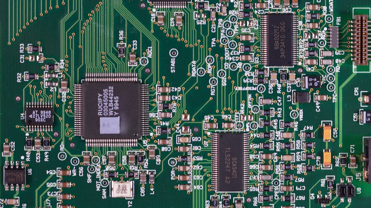
The NXP TJA1051 CAN transceiver acts as a bridge. It converts the logical signals from a CAN controller into physical signals for the CAN bus. It also translates incoming bus signals back into logical signals for the controller. This process ensures reliable data transmission. The TJA1051 has a specific pinout for its operations.
|
Pin Number |
Symbol |
Description |
|---|---|---|
|
1 |
TXD |
Transmit data input |
|
2 |
GND |
Ground |
|
3 |
VCC |
Supply voltage |
|
4 |
RXD |
Receive data output; reads out data from the bus lines |
|
5 |
VIO |
Supply voltage for I/O level adapter; TJA1051T/3 and TJA1051TK/3 only |
|
6 |
CANL |
LOW-level CAN bus line |
|
7 |
CANH |
HIGH-level CAN bus line |
|
8 |
S |
Silent mode control input |
Key Features for Automotive Reliability
Automotive environments are harsh. NXP designs its components for these tough conditions. The NXP TJA1051 for automotive CAN bus communication includes features that ensure reliability.
-
Enhanced Protection: It offers superior protection against electromagnetic and electrostatic disturbances. This is crucial for complex automotive electronic networks.
-
Electromagnetic Robustness: The transceiver features reduced electromagnetic emissions. It also has high resilience to electromagnetic interference. This ensures stable performance near other devices and minimizes data errors.
-
Voltage Compatibility: It operates seamlessly with microcontrollers from 3V to 5V. This allows adaptability to various automotive subsystems.
-
Standard Compliance: The device adheres to ISO 11898-2:2016 standards. This guarantees robust data exchange and safe implementation.
-
High Data Rates: It supports data rates up to 5 Mbps. This suits high-speed CAN environments needing swift and dependable communication.
-
Robust Protection Features: It includes safeguards against voltage fluctuations and potential damage. This maintains network operation even in harsh conditions.
TJA1051 Variants and Use Cases
The TJA1051 high-speed CAN transceiver comes in different versions. Pin 5’s function is the sole distinction among them.
|
TJA1051 Variant |
Pin 5 Functionality |
|---|---|
|
TJA1051T/E |
EN (enable control input) |
|
TJA1051T/CM |
Not connected |
|
TJA1051T |
Does not have EN pin (implied not connected or different from /E) |
For the TJA1051T/3 and TJA1051TK/3 variants, Pin 5 serves as VIO. This provides a supply voltage for the I/O level adapter. Pin 8, labeled ‘S’, controls the Silent mode. In Silent mode, the transmitter disables itself. This prevents the transceiver from interfering with the CAN bus.
The TJA1051 is ideal for high-speed CAN networks. These networks do not require a standby mode with wake-up capability. This simplifies system design and helps conserve power. Common applications include:
-
Automotive communication systems
-
Industrial automation
-
Home security systems
These applications all require reliable and fast data exchange. The NXP TJA1051 for automotive CAN bus communication ensures robust data exchange in these critical systems.
Principles of Automotive CAN Bus Communication
CAN Protocol Fundamentals
The controller area network (CAN) protocol forms the backbone of automotive communication. It is a multi-master, message-based protocol. All devices on the can bus can transmit data. Multiple devices can also request to use the bus at the same time. CAN uses a prioritized message system instead of an addressing system. Messages are divided into priority ranges. A transmitting device sends a message to all CAN nodes. Each node then decides how to react. It also determines message priority if multiple messages are sent concurrently.
Arbitration happens during the Arbitration Field. If multiple transmitters send simultaneously, they detect conflicts. This occurs when sending a recessive logic level 1 but observing a dominant level 0 on the can bus. This forces the affected transmitter to delay. It allows the highest priority message to proceed. This process repeats until all messages are sent in order of priority. CAN arbitration resolves bus access conflicts through bit-by-bit comparison. This ensures the message with the lowest identifier remains. It enables efficient and loss-free communication. The message identifier is 11 bits in standard format and 29 bits in extended format. The most significant bit transmits first. Arbitration relies on dominant (overriding, e.g., L level) and recessive (yielding, e.g., H level) bus levels. During arbitration, each sending participant compares its sent bus level with the actual bus level. If a participant sends a recessive bit but observes a dominant bit, it stops transmitting. It then becomes a consumer. Only the participant whose message has the lowest identifier value remains on the can bus. A logical zero is a dominant bus level, making lower identifiers higher priority. This bit-by-bit arbitration ensures only one participant remains on the bus. This results in ‘loss-free’ communication. Messages are small, up to eight data bytes, and protected by a checksum. Messages do not have explicit addresses. Instead, they carry a numeric ID that controls priority and identifies content. A message (Frame) primarily consists of an ID representing priority and up to eight data bytes. It also includes a CRC, acknowledge slot (ACK), and other overhead. Message IDs must be unique. Lower numerical IDs indicate higher message priority.
CAN Physical Layer Requirements
The physical layer of the can bus system defines how signals travel. It uses differential signaling. This means two wires carry the signal. This method helps reduce noise and interference. Different CAN standards support various data rates and voltage levels.
|
Standard |
Max. Voltage |
Data Rate (Mbit/s) |
|---|---|---|
|
CAN 2.0 |
16V DC |
Up to 1 |
|
CAN FD |
16V DC |
Up to 8 |
|
CAN XL |
16V DC |
Up to 20 |
|
ISO 11898-2 (High-speed) |
N/A |
Up to 1 |
|
ISO 11898-3 (Low-speed, fault-tolerant) |
N/A |
0.04 to 0.125 |
|
ISO 11898-5 |
N/A |
Up to 1 |
|
ISO 11898-6 |
N/A |
Up to 1 |
The signal type is differential. ISO 11898-2 uses two-wire balanced signaling. This ensures robust communication even in noisy automotive environments.
Transceiver’s Role in Data Exchange
A CAN transceiver plays a crucial role in reliable data transmission. It converts the single-ended transmit and receive signals (TXD and RXD) from the CAN controller. It changes them into differential signals (CAN high and CAN low). These differential signals then transmit over the physical can bus. This conversion to differential signaling is key for robust communication. The transceiver ensures that the electrical signals are strong and clear. It also protects the CAN controller from electrical disturbances on the bus. This makes the entire can bus network more reliable.
Integrating NXP TJA1051 into Automotive Designs
Integrating the NXP TJA1051 into automotive designs requires careful attention to circuitry, power, and layout. Proper implementation ensures the reliability and performance of the entire can bus network.
Essential Circuitry and Component Selection
Designing a robust CAN interface begins with selecting the right external components and configuring the essential circuitry. A typical application circuit diagram for the NXP TJA1051T/3/2Z shows how to connect the transceiver to a can bus. This diagram includes connections for power supply, ground, and communication bus lines. These connections ensure proper operation and reliable data transmission.
Key external components include:
-
Decoupling Capacitors: Place a 100 nF ceramic capacitor close to the VCC pin of the TJA1051. This capacitor filters high-frequency noise from the power supply, ensuring stable operation.
-
Common-Mode Chokes: These components help reduce electromagnetic interference (EMI) on the CAN lines. Place them on the CANH and CANL lines near the transceiver. They suppress common-mode noise while allowing differential signals to pass through.
-
Termination Resistors: The can bus system requires termination resistors at both ends of the bus. These resistors prevent signal reflections, which can corrupt data. For a standard high-speed CAN bus, use two 120-ohm resistors, one at each end of the bus.
Power Supply Considerations
The NXP TJA1051 operates reliably within specific power supply parameters. The NXP TJA1051 requires a supply voltage of 4.5V to 5.5V. This range ensures the transceiver functions correctly and maintains signal integrity. Designers must ensure the power supply provides a stable voltage within this range. They also need to minimize voltage ripple. Excessive ripple can introduce noise into the system and affect communication quality. Using appropriate voltage regulators and filtering capacitors helps achieve a clean power supply.
PCB Layout Guidelines for Optimal Performance
A well-designed Printed Circuit Board (PCB) layout is crucial for minimizing signal integrity issues and electromagnetic interference (EMI). Following best practices ensures the NXP TJA1051 performs optimally.
-
Bypass Capacitors: Utilize local bypass capacitors. Place them as close as possible to the transceiver’s power pins.
-
ESD and EMI Resilience: Add small-value capacitors, typically 40-100 pF, on CANH and CANL lines. Connect these capacitors to ground. They help absorb electrostatic discharge (ESD) and improve EMI resilience.
-
Split Termination: Implement split termination using two 60-ohm resistors in series. This totals 120 ohms. Connect a 4.7 nF capacitor to ground at the junction of these resistors. This method improves EMI performance.
-
TVS Diodes Placement: Place Transient Voltage Suppressor (TVS) diodes as close as possible to the connector and the board’s edge. This prevents noise coupling and handles high-speed, high-current events effectively.
-
Ground Planes: Employ ground planes directly beneath signals clamped to ground. This ensures a short, low-impedance path for return currents.
-
Low-Impedance Vias: Use low-impedance via techniques, such as vias on the outskirts of pads. This avoids nullifying capacitor effects due to ground trace inductance.
-
Optional ‘Weak’ Termination: Consider optional ‘weak’ termination, for example, 1.3 kOhm, for nodes with long stub distances. This improves EMI resilience. However, designers must be mindful of potential network loading and speed reduction.
-
Advanced Protection: If cost is not a constraint and input protection is paramount, consider a second round of protection with MOVs or GDTs for higher energy absorption. Also, include current-limiting devices. Be aware that this increases bus capacitance and reduces data rates.
Interfacing with Microcontrollers and CAN Controllers
The NXP TJA1051 transceiver acts as a bridge. It connects the CAN protocol controller to the physical two-wire can bus. This functionality is crucial for managing complex data streams within automotive systems. It optimizes data exchange and system performance across various applications. The TJA1051 is a high-speed CAN transceiver. It provides an interface between a CAN protocol controller and the physical two-wire CAN bus. It supports both 3.3V and 5V microcontrollers (MCUs). Block diagrams are available for interfacing with both 3.3V and 5V MCUs. This flexibility allows designers to integrate the nxp transceiver tja1051 for automotive can bus communication into diverse automotive electronic control units (ECUs). The transceiver translates the digital signals from the microcontroller’s CAN controller into differential analog signals for transmission over the bus. It also converts incoming bus signals back into digital form for the controller. This seamless conversion ensures reliable communication between different nodes on the can bus.
Advanced Considerations and Best Practices
EMC/EMI Compliance and Mitigation
Automotive environments present significant challenges for electronic components. Electromagnetic compatibility (EMC) and electromagnetic interference (EMI) are critical concerns. Designers must ensure that the NXP TJA1051 and its surrounding circuitry operate without causing or being affected by electromagnetic disturbances.
Automotive CAN transceivers must comply with automotive standards such as ISO 11898. This standard addresses design considerations including electromagnetic compatibility (EMC). It ensures reliable data transfer under harsh conditions. Other important standards include ISO 7637, which offers guidelines for ensuring systems withstand electromagnetic conditions. CISPR 25 outlines test methods and suggested limits for evaluating radiated emissions from vehicle components. Its primary goal is to ensure a component does not interfere with other in-vehicle systems. For immunity testing, ISO 11452-4 specifies bulk current injection (BCI) tests. These tests verify a component’s resilience to narrowband electromagnetic fields. Testing involves inducing disturbance signals directly into wiring harnesses. CISPR 25 is used for radiated emissions testing. It measures electromagnetic fields emitted by the PCB to ensure they remain within defined limits. For example, emissions should be below 30 dBμV/m at 1 meter for frequencies up to 1 GHz. ISO 11452 is employed for immunity testing. It exposes the PCB to external EMI to confirm its operational integrity under field strengths up to 100 V/m.
To mitigate EMC/EMI issues, designers implement several strategies. They use proper grounding techniques, including solid ground planes. Shielding cables and components helps contain electromagnetic fields. Filtering power supply lines and data lines with capacitors and inductors reduces noise. Careful PCB layout, such as keeping high-speed traces short and separated, also minimizes interference.
Thermal Management for Reliability
The NXP TJA1051, like all electronic components, generates heat during operation. Effective thermal management is essential for maintaining its reliability and extending its lifespan. High temperatures can degrade component performance and lead to premature failure.
Factors contributing to heat generation include power dissipation within the transceiver and the ambient temperature of the operating environment. In automotive applications, temperatures can fluctuate widely. Designers must consider these variations.
Proper thermal management involves several techniques. PCB design plays a crucial role. Designers use larger copper areas connected to the transceiver’s ground and power pins. These areas act as heat sinks, dissipating heat away from the component. Strategic placement of the transceiver on the PCB, away from other heat-generating components, also helps. In some cases, external heat sinks or forced air cooling might be necessary, especially in confined spaces or high-power applications. Ensuring good airflow around the component is always beneficial.
Fault Tolerance and Diagnostic Features
Robust automotive systems require fault tolerance. This means the system can continue to operate even when a component fails or experiences an error. The NXP TJA1051 incorporates several fault tolerance features to enhance network reliability.
The TJA1051 is short-circuit protected. It also features thermal shutdown. These protections extend to the bus pins, offering bus-pin short-circuit protection and bus-pin thermal shutdown. These features protect the transceiver and the entire can bus system from damage due to electrical faults. For example, if a short circuit occurs on the CAN bus lines, the transceiver automatically limits the current to prevent overheating and damage. If the transceiver’s internal temperature exceeds a safe limit, the thermal shutdown feature temporarily disables the device. This prevents permanent damage. Once the temperature returns to a safe level, the transceiver can resume normal operation.
The TJA1051 also offers diagnostic capabilities. These include error flags and status registers. These features allow the CAN controller to monitor the transceiver’s health and detect potential issues. This helps in identifying and troubleshooting problems within the can bus network.
Testing and Validation of CAN Bus Integration
Thorough testing and validation are crucial steps for ensuring the reliability and meeting the performance requirements of any can bus integration. This process confirms the system operates correctly under various conditions.
Designers start by choosing the right hardware and software tools. They select appropriate CAN bus interfaces and diagnostic tools compatible with testing requirements. They consider interface compatibility, supported protocols, data logging, and real-time monitoring features. Next, they configure the test setup. This involves establishing physical connections between test equipment and the can bus network. They follow manufacturer guidelines for reliable communication and accurate results. Establishing communication involves initializing CAN bus interfaces, configuring communication parameters, and verifying connectivity. Diagnostic software often helps monitor traffic and send test messages.
Simulating real-world conditions assesses system performance under various scenarios, such as induced noise. This ensures reliability and stability in adverse conditions. Documentation and validation are also vital. Maintaining detailed records of test setups, procedures, parameters, cases, and results ensures repeatability, traceability, and compliance with industry standards.
Analyzing network traffic involves using diagnostic tools to capture and analyze CAN bus traffic in real-time. This helps observe message transmission, identify patterns, and detect anomalies. Decoding CAN messages employs diagnostic software to interpret message content, identify types, and analyze patterns. This diagnoses communication issues. Troubleshooting involves conducting fault isolation tests, continuity checks, and verifying individual node functionality. This identifies and addresses root causes of communication issues. Error frames and diagnostic messages provide insights into network health and performance. They help identify communication errors. Implementing error handling mechanisms involves designing fault-tolerant systems with error detection, correction, and recovery techniques. This reduces the impact of communication errors.
Diagnostic software tools, such as Vector CANalyzer, PCAN-View, and Kvaser CANtrace, offer advanced capabilities. These include real-time monitoring, message decoding, data logging, event logging, and automated diagnostics. Documenting diagnostic procedures involves keeping detailed records of procedures, test setups, parameters, results, and corrective actions. This ensures repeatability, traceability, and future reference.
Specific tests include waveform testing, performed with an oscilloscope. This analyzes amplitude, edge time, overshoots, undershoots, and rise/fall times against protocol standards. An eye diagram test uses an oscilloscope to view digital circuit responses over time. It analyzes eye height, eye width, and noise tolerance to assess signal quality. A jitter test quantifies signal cycle jitter and timing offsets using a time interval analyzer. This locates clock signal stability problems. A TDR test (Time Domain Reflectometry) is used for PCB signal lines and device impedance testing. This includes single-ended and differential signal lines and connector cables. A timing test synchronizes measurement of parameters like signal delay and clock skew. This verifies timing window matching for parallel buses. Spectrum testing utilizes a spectrum analyzer to detect signal harmonics, spurious noise, and other frequency domain characteristics. This identifies EMI sources. A frequency domain impedance test employs a vector network analyzer (VNA) to measure transmission line impedance characteristics at different frequencies. A transmission line loss test measures signal attenuation in PCB alignments using a VNA or TDR. This assesses link loss for high-frequency signals.
Tools like oscilloscopes visualize CAN bus signals. They detect anomalies like noise, voltage spikes, or distorted waveforms. They also analyze signal integrity. A CAN bus analyzer provides real-time insights into network performance. It monitors CAN traffic, identifies error frames, and decodes messages to pinpoint issues. Diagnostic software is essential for identifying and resolving CAN bus transceiver issues by analyzing error codes. Physical inspection involves examining physical connections and wiring. Voltage level measurement uses a multimeter to check voltage levels on CAN Hi and CAN Lo lines. Error frame analysis involves monitoring error frames to identify root causes.
The nxp transceiver tja1051 for automotive can bus communication plays an indispensable role in enabling reliable and efficient automotive can bus networks. Careful design and implementation, as discussed throughout this blog, are paramount for creating robust in-vehicle can bus systems. Engineers should leverage the TJA1051’s advanced capabilities for their automotive projects, reinforcing its status as a cornerstone component for can bus reliability. For further details on enhancing can bus designs, explore NXP’s official datasheets and application notes.
See Also
NXP Microcontrollers: Powering Automotive Electronics with In-Depth Analysis and Applications
MC9S12XET512VAG Microcontroller: Automotive System Integration Strategy and Practical Analysis
Exploring FREESCALE MCF5251CVM140: Unveiling Its Essential Automotive Features
AD9736BBCZ: Shaping the Future of Wireless Communication Technology
MC9S12DJ256MFUE: Comprehensive Exploration and Hands-On Implementation in Automotive Electronics
