Automation systems often rely on efficient integration between PNP and NPN PLC modules. A 24V system simplifies this process by providing a standardized voltage level, minimizing errors during installation. This approach ensures seamless communication between components, reducing downtime and boosting operational reliability. Engineers benefit from its ability to accommodate diverse sensors and input modules without complex rewiring. When asked, “Will this circuit work to interface both PNP and NPN PLC input modules with a 24V system?” the answer lies in its robust design and compatibility. This solution enhances overall productivity in industrial setups.
Key Takeaways
-
Knowing PNP and NPN modules is important for PLC systems. These modules control current flow and help sensors talk to PLCs.
-
A 24V system makes wiring easier and works with more devices. This setup lowers mistakes and makes automation systems more dependable.
-
Signal converters are needed for mixed systems. They help PNP and NPN devices work together and make integration easier.
-
Good wiring stops problems like wrong polarity or loose wires. Using proper wiring rules keeps the system working well.
-
Testing and maintenance keep systems running better. Engineers should fix issues and check connections for long-term success.
What Are PNP and NPN Modules in PLC Systems?
Defining PNP and NPN Modules
PNP and NPN modules are essential components in PLC systems, enabling the connection and control of various input devices. These modules act as interfaces between the PLC and external devices, such as sensors or switches, by managing the flow of current. The terms PNP and NPN refer to the type of transistor configuration used within the module.
PNP modules allow current to flow from the positive terminal to the negative terminal, while NPN modules enable current flow in the opposite direction. This distinction determines how the modules interact with the PLC input and external devices. For example, PNP modules are often referred to as “sourcing” modules because they supply current to the input device. In contrast, NPN modules are known as “sinking” modules, as they draw current from the input device.
To better understand the technical specifications of these modules, consider the following table:
|
Parameter |
Value |
|---|---|
|
Type number |
|
|
Package version |
SOT1118 |
|
Package name |
DFN2020-6 |
|
Size (mm) |
2 x 2 x 0.65 |
|
Channel type |
NPN/PNP |
|
Configuration |
2 |
|
Ptot (mW) |
370 |
|
VCEO [max] (V) |
60 |
|
IC [max] (mA) |
1000 |
|
hFE [min] |
290 |
|
TJ [max] (°C) |
150 |
|
fT [min] (MHz) |
90 |
|
Automotive qualified |
No |
This table highlights the versatility of modules that support both PNP and NPN configurations, making them suitable for diverse PLC input requirements.
Key Differences Between PNP and NPN Modules
Understanding the differences between PNP and NPN modules is crucial for selecting the right module for a specific application. These differences lie in their electrical characteristics, current flow, and typical use cases.
|
Feature |
NPN Transistor |
PNP Transistor |
|---|---|---|
|
Charge Carriers |
Electrons |
Holes (absence of electrons) |
|
Current Flow |
From emitter to collector through base |
From emitter to collector through base |
|
Advantages |
Rapid switching, high efficiency |
High voltage handling, inverse current flow |
|
Applications |
Low-side switching, digital circuits |
High-side switching, power distribution |
NPN modules are widely used in digital circuits due to their fast switching capabilities and high efficiency. On the other hand, PNP modules excel in high-side switching applications, where they handle higher voltages and provide inverse current flow. These distinctions make it easier to determine which module suits a particular PLC input configuration.
Applications of PNP and NPN Modules in PLC Systems
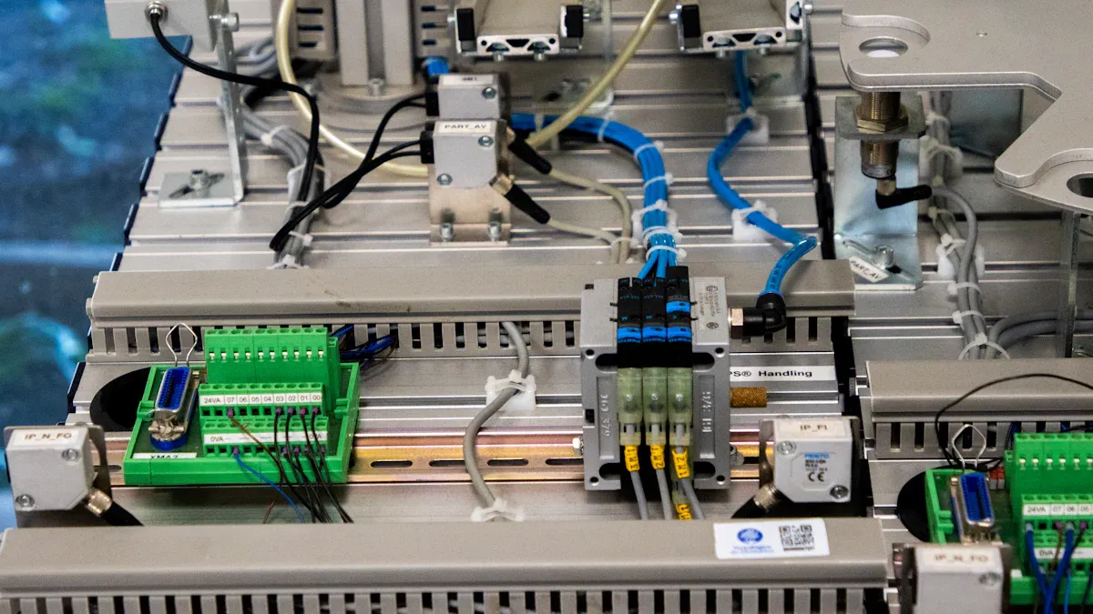
PNP and NPN modules play a vital role in various industrial automation applications. They connect PLC input devices, such as sensors, switches, and relays, to the control system. PNP modules are commonly used with sourcing sensors, which provide a positive voltage signal to the PLC input. These modules are ideal for applications requiring high-side switching, such as power distribution systems.
NPN modules, on the other hand, are compatible with sinking sensors, which send a negative voltage signal to the PLC input. These modules are often found in low-side switching applications, such as digital circuits and logic gates. Their rapid switching capabilities make them suitable for high-speed operations in industrial environments.
In mixed systems, where both PNP and NPN sensors are present, engineers can use versatile modules that support both configurations. This flexibility simplifies the integration process and ensures seamless communication between the PLC and external devices. By selecting the appropriate module for each application, engineers can optimize the performance and reliability of their PLC systems.
Will This Circuit Work to Interface Both PNP and NPN PLC Input Modules with a 24V System?
Understanding Circuit Design for Mixed Systems
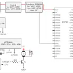
Designing a circuit that interfaces both PNP and NPN PLC input modules requires careful consideration of current flow and signal integrity. Mixed systems often include sensors and devices with differing electrical characteristics. Engineers must ensure that the circuit accommodates both sourcing and sinking configurations without compromising performance.
A versatile circuit design achieves this by incorporating components that adapt to the unique requirements of PNP and NPN modules. For example, the inclusion of signal converters allows the circuit to process both positive and negative voltage signals effectively. This ensures seamless communication between the PLC and external devices, regardless of their configuration.
Additionally, scalability plays a crucial role in mixed systems. A well-designed circuit supports testing across various device functions, including digital, RF, analog, and power. This flexibility simplifies integration and reduces the need for multiple test setups.
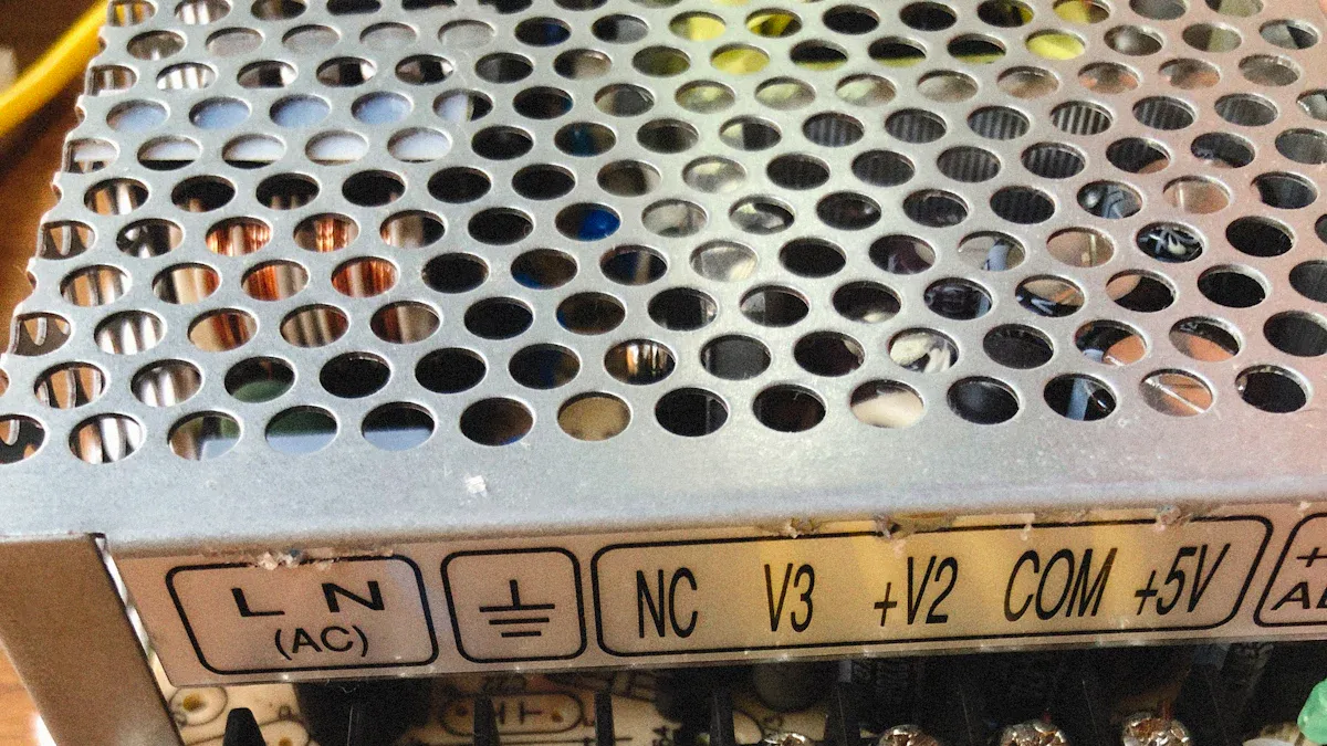
Ensuring Compatibility with a 24V System
Compatibility with a 24V system is essential for reliable operation in industrial environments. The circuit must handle the voltage efficiently while maintaining signal integrity. Engineers achieve this by using components optimized for 24V systems, such as power supplies and transceivers.
For instance:
-
The Analog solution includes two on-board power supplies for the digital interface, ensuring smooth operation with a 24V supply.
-
The MAX16904 component steps down the 24V voltage to 5V, minimizing power dissipation during high-speed communications.
-
The MAX22500E RS-485 transceiver operates at data rates up to 100Mbps, making it ideal for motion control applications with high electromagnetic compatibility.
These features ensure that the circuit performs effectively in demanding conditions. Compatibility with existing load boards and instruments further simplifies the transition to a 24V system, maintaining performance standards across the setup.
Benefits of Using a Versatile Circuit for Integration
A versatile circuit offers several advantages when integrating PNP and NPN PLC input modules with a 24V system. First, it reduces complexity by supporting both sourcing and sinking configurations. Engineers can connect PNP and NPN sensors without extensive rewiring or additional components.
Second, the circuit enhances operational efficiency. By accommodating diverse device functions, it streamlines testing and troubleshooting processes. This saves time and resources, allowing engineers to focus on optimizing system performance.
Third, the robust design of the circuit ensures long-term reliability. Components like the MAX16904 and MAX22500E are engineered for high-speed and high-EMC applications, making them suitable for industrial environments. The ability to handle mixed systems with ease further boosts the circuit’s value in automation projects.
Finally, scalability ensures that the circuit adapts to evolving requirements. Whether testing digital, RF, analog, or power functions, the circuit provides a reliable platform for integration. This versatility makes it an indispensable tool for engineers working with PNP and NPN PLC input modules in a 24V system.
Wiring Configurations for PNP and NPN Modules
Standard Wiring for PNP Modules
PNP modules, often referred to as sourcing modules, supply current to the connected device. Proper wiring ensures the module operates efficiently within a PLC system. In a standard configuration, the positive terminal of the power supply connects to the sensor’s positive lead. The sensor’s output wire then connects to the PLC input terminal. Finally, the negative terminal of the power supply links to the PLC’s common ground.
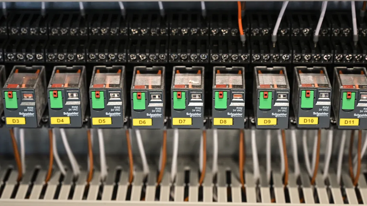
This setup allows the PNP module to provide a positive voltage signal to the input terminal when activated. Engineers often use this configuration in applications requiring high-side switching, such as powering relays or actuators. Ensuring tight and secure connections minimizes the risk of signal loss or interference.
Standard Wiring for NPN Modules
NPN modules, known as sinking modules, draw current from the connected device. Their wiring differs slightly from PNP modules. In a typical setup, the sensor’s negative lead connects to the negative terminal of the power supply. The sensor’s output wire links to the PLC input terminal, while the positive terminal of the power supply connects to the PLC’s common ground.
This configuration enables the NPN module to send a negative voltage signal to the input terminal when activated. NPN modules are commonly used in low-side switching applications, such as digital circuits or logic gates. Proper grounding is critical in this setup to prevent voltage fluctuations and ensure stable operation.
Avoiding Common Wiring Errors
Incorrect wiring can lead to system malfunctions or even damage to components. Common errors include reversed polarity, loose connections, and improper grounding. To avoid these issues, engineers should follow a systematic troubleshooting process:
|
Step |
Description |
|---|---|
|
1 |
Observe the system operation and faults |
|
2 |
Clearly understand the problem |
|
3 |
Gather any additional information |
|
4 |
Isolate the problem |
|
5 |
Hypothesize a cause(s) |
|
6 |
Use the cause to determine the probability of its effect and other expected observations |
|
7 |
Perform experimental tests to determine the validity of your hypothesis |
Failures in proven systems often result from operator error, bad wiring, or power supply issues. In unproven systems, wiring problems and defective components are common culprits. Engineers should double-check connections, verify power supply ratings, and ensure proper configuration to maintain system integrity.
By adhering to these practices, engineers can prevent wiring errors and ensure reliable operation of PNP and NPN modules within PLC systems.
Practical Techniques for Seamless Integration
Using Signal Converters for Mixed Systems
Signal converters play a crucial role in integrating mixed systems that involve both pnp and npn sensors. These converters enable seamless communication between devices with differing electrical configurations. For example, a pnp to npn conversion allows a sourcing sensor to interact with a sinking input module, while an npn to pnp conversion achieves the reverse. This flexibility ensures compatibility across diverse setups.
Testing has shown that signal converters maintain high efficiency under various conditions. The table below highlights their performance:
|
Condition |
Efficiency Curve |
Description |
|---|---|---|
|
Normal Operation Conditions |
Blue Curve |
Represents efficiency under standard load conditions. |
|
Communication-Integrated |
Red Curve |
Shows efficiency when data modulation is integrated, indicating no additional power consumption. |
By using these converters, engineers can simplify the integration process and ensure reliable output signals from both pnp and npn sensors.
Testing and Troubleshooting Connections
Thorough testing and troubleshooting are essential for ensuring the reliability of integrated systems. Engineers should focus on key performance metrics to validate system functionality. These include load testing to assess behavior under normal and peak conditions, stress testing to evaluate performance under extreme scenarios, and endurance testing to measure long-term stability.
Neglecting proper testing can lead to unreliable systems and poor user experiences. Engineers should also analyze connections for potential issues, such as loose wiring or improper grounding. A systematic approach to troubleshooting includes isolating the problem, hypothesizing potential causes, and conducting experimental tests to confirm the diagnosis. This process ensures that both pnp and npn sensors operate efficiently within the plc system.
Best Practices for Long-Term Reliability
Maintaining long-term reliability requires adherence to best practices. Proper resource management prevents system failures, while secure coding practices ensure stability. For instance, placing cleanup code in a finally block guarantees execution regardless of exceptions. Using tools like SafeHandle helps manage operating system resources and prevents leaks during application unloads.
Additionally, implementing stringent security measures enhances system durability. These include role-based access control, multi-factor authentication, and continuous monitoring for vulnerabilities. Network segmentation and secure remote access protocols further protect the system from external threats. By following these practices, engineers can ensure that pnp and npn sensors deliver consistent performance over time.
Addressing Challenges in Mixed PNP and NPN Systems
Managing Voltage Compatibility and Signal Integrity
Mixed systems with PNP and NPN sensors often face voltage compatibility challenges. Ensuring proper voltage levels is critical for maintaining signal integrity and preventing malfunctions. Engineers must verify that all components operate within the 24V system’s range. Using voltage regulators or step-down converters can help stabilize power supply fluctuations. For example, a MAX16904 regulator efficiently steps down 24V to 5V, ensuring smooth operation for sensitive components.
Signal integrity also depends on minimizing noise and interference. Shielded cables and proper grounding techniques reduce electromagnetic interference (EMI). Additionally, engineers should avoid long cable runs, as these can degrade signal quality. Testing the system under various load conditions ensures that voltage levels remain stable and signals are transmitted accurately.
Avoiding Ground Loop Issues
Ground loops occur when multiple ground connections create a difference in potential, leading to unwanted current flow. These loops can cause erratic behavior in PLC systems, especially in mixed configurations with PNP and NPN sensors. To prevent this, engineers should establish a single-point grounding system. This approach ensures that all components share a common reference point, eliminating potential differences.
Isolation techniques, such as using optocouplers or isolation transformers, further mitigate ground loop risks. These devices separate the electrical paths of different components while maintaining signal transmission. Proper cable management, including separating power and signal lines, also reduces the likelihood of ground loops. Regular inspections of grounding connections help maintain system stability over time.
Ensuring Operational Efficiency in Mixed Systems
Operational efficiency in mixed systems depends on optimizing internal processes and evaluating performance metrics. Engineers can use tools like the Balanced Scorecard or Objectives and Key Results (OKRs) to track progress. Key metrics include productivity ratios, operational efficiency, and cost efficiency. The table below highlights these metrics:
|
Metric Type |
Description |
|---|---|
|
Productivity Ratios |
Measure output generated per unit of input, e.g., units produced per labor hour. |
|
Operational Efficiency |
Assesses effectiveness of internal processes, e.g., cycle time and throughput time. |
|
Cost Efficiency |
Evaluates management of expenses relative to output, e.g., cost per unit and ROI. |
By focusing on these metrics, engineers can identify bottlenecks and improve system performance. Regular maintenance of sensors and PLC components ensures consistent output. Testing under peak and normal conditions helps validate the system’s reliability, while streamlined workflows enhance overall productivity.
Understanding PNP and NPN modules is essential for building efficient PLC systems. These modules determine how current flows and interact with sensors, ensuring accurate output in automation processes. Integrating them with a 24V system simplifies wiring and enhances compatibility, making it easier to manage mixed configurations.
Key takeaways include the importance of proper wiring, using signal converters for mixed systems, and maintaining voltage stability. Engineers should prioritize testing and troubleshooting to ensure reliable output. Regular maintenance and adherence to best practices will further enhance system performance and longevity.
What is the role of PNP and NPN modules in PLC systems?
PNP and NPN modules manage current flow between sensors and PLC inputs. They enable sourcing or sinking configurations, ensuring accurate signal transmission. These modules play a critical role in automation by facilitating seamless communication between devices.
Can a single circuit handle both PNP and NPN modules?
Yes, a versatile circuit can interface both types of modules. It adapts to sourcing and sinking configurations, ensuring compatibility. This design simplifies integration and enhances the output of mixed systems.
How does a 24V system improve PLC integration?
A 24V system standardizes voltage levels, reducing wiring complexity. It ensures stable power delivery and minimizes errors. This setup enhances the reliability and output of automation systems.
What are common wiring mistakes with PNP and NPN modules?
Reversed polarity, loose connections, and improper grounding are frequent errors. These issues can disrupt the output and damage components. Engineers should double-check connections and follow standard wiring practices.
Why are signal converters important in mixed systems?
Signal converters enable communication between devices with different configurations. They ensure accurate output by converting signals between sourcing and sinking modes. This flexibility simplifies integration and improves system performance.
See Also
Uncover The Benefits Of LPQ252-CEF In Power Management
Three Effective Methods To Incorporate MC9S12XET512VAG
Understanding MC9S12DJ256MFUE Specs For Automotive Use
Ways EP2C50F484I8N FPGA Can Revolutionize Your Projects
Key Programming Techniques For MC9S12XD256 Microcontrollers