Resistor color codes make it easier to determine the resistor value quickly and accurately. This universal system relies on colored bands to represent numerical values, ensuring precision in electronic applications. Each band provides essential details about the resistor, such as its resistor value or tolerance. By mastering the resistor color code, both engineers and hobbyists can design circuits efficiently and troubleshoot problems with confidence. Whether you’re working on a new project or fixing an existing one, understanding the resistor color code system is crucial for achieving dependable results.
Key Takeaways
-
Resistor color codes use stripes to show resistance values. This helps you identify them without special tools.
-
Knowing the resistor color chart is important for correct calculations. It also helps you pick the right parts for circuits.
-
Always read the resistor from left to right. Start with the tolerance stripe on the far right to avoid mistakes.
-
Use memory tricks or flashcards to learn the color codes. This makes it easier to figure out resistor values fast.
-
A multimeter is a helpful tool to check resistor values. It ensures your electronic projects are accurate.
Understanding Resistor Color Codes
What Are Resistor Color Codes and Their Purpose?
Resistor color codes are a standardized system used to identify the resistance, tolerance, and other characteristics of resistors. This system simplifies the process of determining resistor values without the need for additional tools. Each resistor features a series of colored bands, with each color representing a specific numerical value or multiplier. This method ensures consistency and accuracy in electronic design and troubleshooting.
The origin of resistor color codes dates back to the 1920s when the Radio Manufacturer’s Association (RMA) introduced this system to address inconsistencies in component labeling. Before this, manufacturers used various methods to mark resistors, leading to confusion. The RMA standardized the use of color bands, selecting colors from the visible spectrum while omitting indigo due to common perception issues. Over time, the International Electrotechnical Commission refined this system by defining the E-series standard values, ensuring global uniformity in resistor manufacturing.
The Resistor Color Code Chart Explained
The resistor color code chart is a visual guide that helps decode the information provided by the colored bands on a resistor. This chart assigns specific numerical values, multipliers, and tolerances to each color. For example, black represents 0, brown represents 1, and red represents 2. The chart also includes gold and silver bands, which indicate tolerance levels, such as ±5% or ±10%.
|
Color Code Type |
Description |
Example |
Resistance Value |
Tolerance |
Temperature Coefficient |
|---|---|---|---|---|---|
|
Four-band |
Most common, uses four bands to represent resistance value, tolerance, and temperature coefficient. |
Brown, Black, Red, Gold |
1.0 kΩ |
5% |
250 ppm/°C |
|
Five-band |
Used for more precise values, uses five bands. |
Brown, Black, Black, Red, Gold |
10Ω |
5% |
250 ppm/°C |
|
Six-band |
For even more precise values, uses six bands. |
Brown, Black, Black, Brown, Red, Gold |
100Ω |
1% |
100 ppm/°C |
The chart is essential for interpreting resistor values accurately. It provides a quick reference for engineers and hobbyists, ensuring they can select the correct resistor for their circuits. By memorizing the resistor color code chart, users can save time and reduce errors during the design process.
How Resistor Color Codes Represent Resistor Values
Resistor color codes use a combination of significant digits, a multiplier, and a tolerance band to represent resistance values. The first two or three bands (depending on the type) indicate the significant digits of the resistor value. The next band serves as the multiplier, determining the power of ten by which the significant digits are multiplied. The final band represents the tolerance, which indicates the acceptable range of variation in the resistor’s resistance.
For example, a four-band resistor with the colors brown, black, red, and gold represents a resistance of 1.0 kΩ with a tolerance of ±5%. The first two bands (brown and black) correspond to the digits 1 and 0. The red band acts as the multiplier, indicating that the significant digits should be multiplied by 100. The gold band specifies the tolerance.
The E-series standard values play a crucial role in this system. These values are logarithmically spaced to ensure a consistent selection of resistor values across different ranges. This standardization simplifies the manufacturing process and ensures compatibility between components. By understanding how resistor color codes represent resistor values, users can confidently select the appropriate resistor for their needs.
The Role of Multiplier and Tolerance Bands
The multiplier and tolerance bands play a crucial role in determining the resistance value and accuracy of a resistor. These bands provide essential information that helps users calculate the exact resistance and understand the acceptable range of variation in its value.
The Multiplier Band: Scaling the Resistance Value
The multiplier band indicates the factor by which the significant digits of a resistor’s value should be multiplied. This band is typically the third or fourth band on a resistor, depending on whether it is a four-band or five-band resistor. Each color in the multiplier band corresponds to a power of ten. For example:
-
Red represents (10^2) or 100.
-
Orange represents (10^3) or 1,000.
-
Green represents (10^5) or 100,000.
To calculate the resistance, multiply the significant digits by the value of the multiplier band. For instance, a resistor with the color bands yellow, violet, and red has significant digits of 4 and 7 (yellow = 4, violet = 7). The red multiplier band ((10^2)) means the resistance is (47 times 100 = 4,700 , Omega) or 4.7 kΩ.
The Tolerance Band: Defining Accuracy
The tolerance band indicates the precision of the resistor’s value. It shows the percentage by which the actual resistance may vary from the stated value. This band is usually the last one on the resistor and is often gold or silver.
-
Gold represents a tolerance of ±5%.
-
Silver represents a tolerance of ±10%.
For example, a resistor with a calculated resistance of 4.7 kΩ and a gold tolerance band has an actual resistance that could range between (4.7 , text{k}Omega times (1 – 0.05)) and (4.7 , text{k}Omega times (1 + 0.05)). This means the resistance could vary between 4.465 kΩ and 4.935 kΩ.
Why These Bands Matter
The multiplier band ensures that resistors can represent a wide range of values without requiring excessively large or small physical components. The tolerance band, on the other hand, provides insight into the resistor’s reliability and suitability for specific applications. For circuits requiring high precision, resistors with tighter tolerances (e.g., ±1%) are preferred. In less critical applications, resistors with wider tolerances (e.g., ±10%) may suffice.
Tip: Always consider the resistor tolerance when designing circuits. It ensures the circuit performs as expected, even with slight variations in resistance.
By understanding the role of the multiplier and tolerance bands, users can confidently decode resistor values and select components that meet their design requirements.
Step-by-Step Guide to Reading Resistor Color Codes

Step 1: Orient the Resistor for Proper Reading
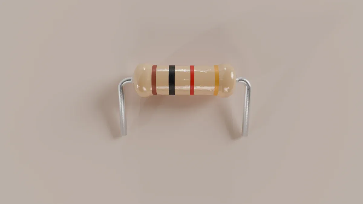
Before decoding the resistor color codes, it is essential to orient the resistor correctly. Resistors have a series of colored bands that represent their resistance values. These bands must be read from left to right. To determine the correct orientation, look for the tolerance band, which is typically gold or silver. This band is always positioned on the far right. Once the resistor is oriented with the tolerance band on the right, the remaining bands can be read in sequence from left to right.
For example, a four color band resistor with the colors brown, black, red, and gold should be oriented so that the gold band is on the far right. This ensures accurate reading of the resistor value. Proper orientation is crucial for avoiding errors when interpreting the resistor color code chart.
Tip: If the resistor has no tolerance band, the orientation can be determined by the spacing between the bands. The side with the wider gap usually indicates the tolerance band.
Step 2: Decode the Significant Digit Bands
The first two or three bands on a resistor represent the significant digits of its resistance value. For a four color band resistor, the first two bands indicate the significant digits. For a five color band resistor, the first three bands represent the significant digits. Each color corresponds to a specific number, as shown in the resistor chart.
To decode the significant digit bands, refer to the resistor color code chart. For instance:
-
Black = 0
-
Brown = 1
-
Red = 2
-
Orange = 3
For a resistor with the colors yellow, violet, and black, the significant digits are 4 (yellow) and 7 (violet). If it is a five color band resistor, the third band (black) adds a third digit, making the significant digits 470.
Step 3: Apply the Multiplier Band to Calculate Resistance
The multiplier band determines the power of ten by which the significant digits are multiplied. This band is typically the third band on a four color band resistor or the fourth band on a five color band resistor. Each color in the multiplier band corresponds to a specific factor, as outlined in the resistor color chart. For example:
-
Red = (10^2) or 100
-
Orange = (10^3) or 1,000
-
Green = (10^5) or 100,000
To calculate the resistance, multiply the significant digits by the multiplier. For example, a resistor with the colors yellow, violet, and red has significant digits of 4 and 7 (yellow = 4, violet = 7). The red multiplier band ((10^2)) means the resistance is (47 times 100 = 4,700) ohms or 4.7 kΩ.
For a five color band resistor, the process is similar. A resistor with the colors brown, black, black, orange, and gold has significant digits of 1, 0, and 0 (brown = 1, black = 0, black = 0). The orange multiplier band ((10^3)) means the resistance is (100 times 1,000 = 100,000) ohms or 100 kΩ.
Note: The multiplier band allows resistors to represent a wide range of resistance values, from a few ohms to several megaohms. This flexibility is essential for meeting the diverse requirements of electronic circuits.
By following these steps, anyone can decode resistor color codes accurately. Understanding the resistor color code system and using the resistor color code chart ensures precise calculation of resistance values, whether working with a four color band resistor, a five color band resistor, or even a six color band resistor.
Step 4: Interpret the Tolerance Band for Accuracy
The tolerance band on a resistor provides critical information about its accuracy. This band indicates the percentage by which the actual resistance may vary from the stated value. It is typically the last band on the resistor and is often gold or silver. Understanding this band ensures that the resistor values meet the required precision for a circuit.
Common Tolerance Band Colors and Their Meanings:
-
Gold: ±5% tolerance
-
Silver: ±10% tolerance
-
No Band: ±20% tolerance
For example, a resistor with a calculated resistance of 1,000 ohms and a gold tolerance band has an actual resistance that could range between 950 ohms and 1,050 ohms. This range is determined by multiplying the resistance by the tolerance percentage. In this case, (1,000 times 0.05 = 50), so the resistance can vary by ±50 ohms.
The tolerance band is essential for selecting resistors in circuits where precision is critical. For high-accuracy applications, resistors with tighter tolerances, such as ±1%, are preferred. In less demanding scenarios, resistors with wider tolerances, like ±10%, may suffice.
Tip: Always consider the tolerance band when choosing a resistor. It ensures the circuit operates within the desired parameters, even with slight variations in resistance.
Example: Reading a 4-Band and 5-Band Resistor
Example 1: Reading a Four Color Band Resistor
Consider a four color band resistor with the colors yellow, violet, red, and gold. Follow these steps to decode its resistance:
-
Significant Digits: The first two bands represent the significant digits. Yellow corresponds to 4, and violet corresponds to 7.
-
Multiplier: The third band, red, indicates a multiplier of (10^2) or 100.
-
Tolerance: The fourth band, gold, represents a tolerance of ±5%.
Using the resistor color chart, calculate the resistance:
[ 47 times 100 = 4,700 , text{ohms} , (text{or } 4.7 , text{k}Omega) ]
The tolerance band indicates the actual resistance could range between (4,700 times 0.95 = 4,465 , text{ohms}) and (4,700 times 1.05 = 4,935 , text{ohms}).
Example 2: Reading a Five Color Band Resistor
Now, consider a five color band resistor with the colors brown, black, black, orange, and gold. Decode its resistance as follows:
-
Significant Digits: The first three bands represent the significant digits. Brown corresponds to 1, black corresponds to 0, and black corresponds to 0.
-
Multiplier: The fourth band, orange, indicates a multiplier of (10^3) or 1,000.
-
Tolerance: The fifth band, gold, represents a tolerance of ±5%.
Using the resistor chart, calculate the resistance:
[ 100 times 1,000 = 100,000 , text{ohms} , (text{or } 100 , text{k}Omega) ]
The tolerance band shows the actual resistance could range between (100,000 times 0.95 = 95,000 , text{ohms}) and (100,000 times 1.05 = 105,000 , text{ohms}).
These examples of reading resistor color codes demonstrate how to interpret both four color band resistors and five color band resistors. By using the resistor color chart and following a systematic approach, anyone can decode resistor values accurately.
Note: For six color band resistors, the process is similar, but the sixth band provides additional information, such as the temperature coefficient.
Common Mistakes and Tips for Reading Resistor Color Codes
Misinterpreting the Resistor Orientation
One common mistake when determining resistor values involves misinterpreting the orientation of the resistor. Resistors feature a series of colored bands that must be read in the correct order. The tolerance band, often gold or silver, always appears on the far right. Reading the bands in reverse order leads to incorrect resistance calculations.
To avoid this error, always identify the tolerance band first. If the resistor lacks a tolerance band, look for a wider gap between the bands. This gap typically indicates the starting point for reading the resistor. Proper orientation ensures accurate interpretation of the resistor color codes.
Tip: Practice identifying the tolerance band on different resistors to build confidence in reading resistor color codes correctly.
Confusing Similar Colors in the Resistor Color Code Chart
Another frequent issue arises from confusing similar colors on the resistor color code chart. Colors like red, orange, and brown or blue and violet can appear similar, especially under poor lighting conditions. Misreading these colors results in incorrect resistor values, which can disrupt circuit performance.
To minimize errors, use a well-lit workspace and, if possible, a magnifying glass to distinguish between similar colors. Familiarity with the resistor color code chart also helps in quickly identifying the correct values. For critical applications, verify the resistance using a multimeter to ensure accuracy.
Note: Consistently working in a well-lit environment reduces the likelihood of misinterpreting colors.
Overlooking the Multiplier Band
Overlooking the multiplier band is another common mistake when calculating resistor values. The multiplier band determines the scale of the resistance, and ignoring it can lead to significant errors. For example, a resistor with significant digits of 4 and 7 and a multiplier of (10^2) has a resistance of 4,700 ohms. Without applying the multiplier, the value would incorrectly appear as 47 ohms.
To avoid this error, always refer to the resistor color code chart and identify the multiplier band before performing calculations. Double-checking the calculated resistance ensures the correct value is used in the circuit.
Tip: Write down the significant digits and multiplier separately before calculating the resistance to avoid skipping any steps.
Tips for Memorizing Resistor Color Codes
Memorizing resistor color codes can seem challenging at first, but several techniques make it easier. These methods help users recall the color-to-value relationships quickly and accurately.
-
Use Mnemonics: Mnemonics are a popular way to memorize the resistor color code sequence. A common example is:
“Black Bears Run Over Yellow Grass But Violet Goats Wander”
This phrase corresponds to the colors: Black (0), Brown (1), Red (2), Orange (3), Yellow (4), Green (5), Blue (6), Violet (7), Gray (8), and White (9). -
Practice with Flashcards: Create flashcards with a color on one side and its corresponding value on the other. Regular practice with these cards reinforces memory and improves speed.
-
Visualize the Chart: Keep a resistor color code chart nearby while working on circuits. Over time, repeated exposure to the chart helps users internalize the values.
-
Group Similar Colors: Focus on distinguishing similar colors like red, orange, and brown. Associating each color with a unique object or image can make them easier to remember.
-
Use Online Tools or Apps: Many apps and websites offer interactive tools for learning resistor color codes. These resources provide quizzes and visual aids to enhance learning.
Tip: Consistent practice is the key to mastering resistor color codes. Dedicate a few minutes daily to reviewing the chart or using flashcards.
Using a Multimeter to Verify Resistor Values
A multimeter is an essential tool for verifying resistor values. It provides an accurate measurement of resistance, ensuring the resistor matches its labeled value.
-
Set the Multimeter to Resistance Mode: Turn the multimeter dial to the resistance setting, often marked with the Ω symbol. Select the appropriate range if the multimeter does not auto-range.
-
Connect the Probes to the Resistor: Attach the multimeter probes to the resistor leads. Polarity does not matter when measuring resistance, so either probe can connect to either lead.
-
Read the Display: Observe the resistance value displayed on the multimeter screen. Compare this value with the calculated resistance from the color code. The measured value should fall within the tolerance range specified by the resistor.
-
Check for Errors: If the measured value deviates significantly, inspect the resistor for damage or verify the multimeter’s calibration.
Note: Always disconnect the resistor from the circuit before measuring its resistance. This prevents interference from other components and ensures accurate readings.
Using a multimeter not only confirms resistor values but also helps identify faulty components. It is a reliable method for ensuring circuit accuracy and functionality.
Resistor color codes simplify the process of determining resistor values, making them an essential tool in electronics. By using the resistor color code chart, users can decode resistance values accurately and ensure proper circuit performance. This skill prevents malfunctions caused by incorrect resistor values and helps identify faulty components. Accurate resistance measurements also maintain compliance with standards and provide insights into circuit behavior, such as temperature-related changes in resistance.
Practicing resistor color code interpretation enhances confidence and improves circuit design. Regular use of the chart and systematic decoding of resistor values lead to better understanding and precision in electronics troubleshooting. Mastering this skill ensures reliable and efficient electronic device operation.
What is the purpose of resistor color codes?
Resistor color codes provide a quick way to identify resistance values, tolerances, and other characteristics. This system eliminates the need for additional labeling, ensuring consistency and accuracy in electronic components.
How can I memorize the resistor color code chart?
Using mnemonics like “Black Bears Run Over Yellow Grass But Violet Goats Wander” helps. Flashcards and regular practice also improve memory. Visualizing the chart while working on circuits reinforces learning.
Can I use a multimeter to verify resistor values?
Yes, a multimeter measures resistance accurately. Set it to resistance mode, connect the probes to the resistor, and read the displayed value. This ensures the resistor matches its labeled value.
What should I do if I confuse similar colors?
Work in a well-lit area to distinguish colors like red, orange, and brown. A magnifying glass can help. For critical applications, verify the resistance with a multimeter to avoid errors.
Why is the tolerance band important?
The tolerance band indicates how much the actual resistance can vary from the stated value. It ensures the resistor meets the precision required for the circuit, preventing performance issues.
See Also
A Simple Guide to Integrating SN74LVC4245APW Sensors
Reasons to Select Coilcraft XPL2010 for VRM/VRD Applications
Implementing ATA5824C Effectively in Remote Control Systems
Enhancing Process Control with AD74413RBCPZ Unlocking Techniques
IRF820: A Versatile N-Channel MOSFET for Power Management