A Raspberry Pi can effectively control a 5V relay by understanding how to switch a MOSFET to drive a 5V relay from Raspberry Pi. Utilizing a MOSFET as a switch enables safe and efficient management of higher-power devices. For example, the IRL540 MOSFET can handle up to 28 Amps at a gate voltage of 5V, ensuring dependable performance. Incorporating MOSFETs reduces power dissipation and enhances overall circuit efficiency.
Key Takeaways
-
Use a MOSFET to turn a 5V relay on or off. This lets you safely control powerful devices without harming the Raspberry Pi.
-
Pick a MOSFET with a low gate voltage to match the Raspberry Pi’s GPIO pins. This makes the circuit work better and last longer.
-
Add a flyback diode to the relay coil to stop voltage surges. This keeps the MOSFET safe and helps your parts last longer.
How to Switch a MOSFET to Drive a 5V Relay from Raspberry Pi?
Overview of the Circuit
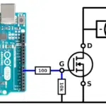
Switching a MOSFET to drive a 5V relay from a Raspberry Pi involves creating a circuit where the MOSFET acts as a low-side switch. This configuration allows the Raspberry Pi GPIO pin to control the relay efficiently. The circuit includes essential components such as resistors, a diode, and the relay itself, all working together to ensure proper operation and protection.
The MOSFET is positioned on the low side of the circuit. This placement simplifies the design by allowing the Raspberry Pi to drive the MOSFET with a small voltage. A resistor (R1) is connected between the GPIO pin and the MOSFET gate to limit the current and prevent delays during startup. Another resistor (R2) is placed between the gate and source terminals to ensure the MOSFET turns off completely when the GPIO pin is low. The voltage across R2 is calculated using a voltage divider formula, ensuring it remains below the MOSFET’s gate threshold voltage for proper operation.
Key performance metrics demonstrate the circuit’s efficiency. For instance, the calculated voltage across R2 is approximately 3.267V, which is suitable for the MOSFET to operate correctly. Additionally, the power dissipation on R2 is minimal, at just 0.227mW, ensuring low energy loss. These factors contribute to a reliable and efficient relay switching mechanism.
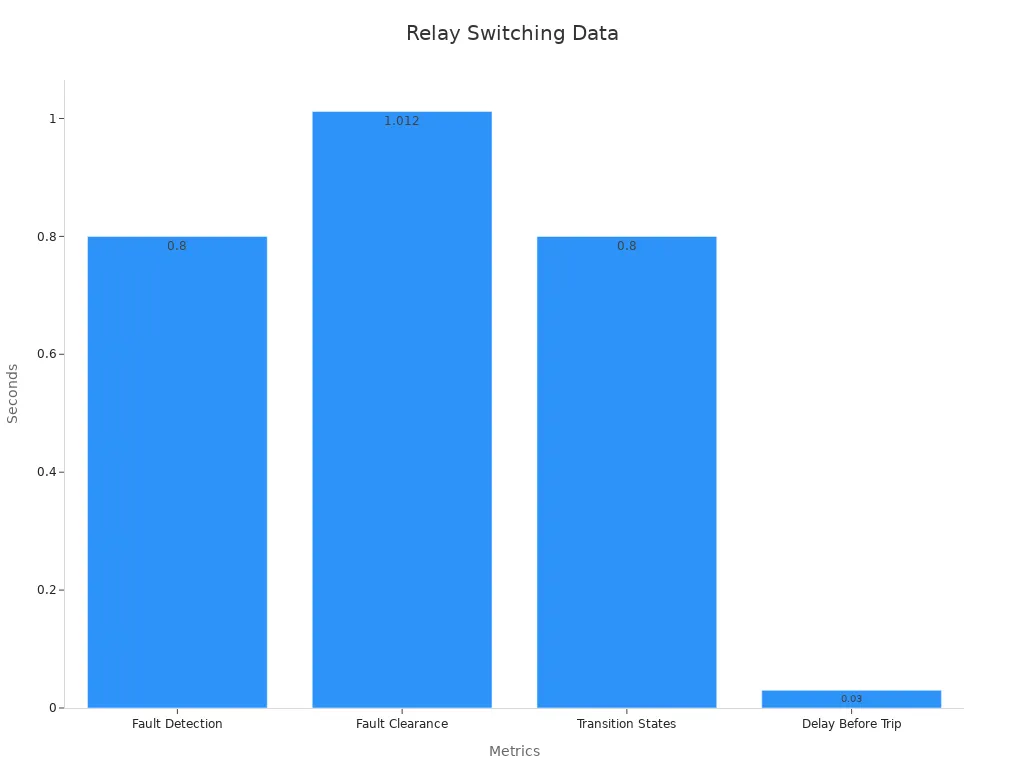
The timing data further highlights the circuit’s performance. The table below summarizes key metrics:
|
Metric/Timing Data |
Description |
|---|---|
|
Fault Detection Time |
Ground fault detected at 0.8 s |
|
Fault Clearance Time |
Fault cleared at 1.012 s |
|
Transition States |
Transition from Idle to Ready at 0.8 s |
|
Delay Before Trip |
0.03 s delay before entering Trip state |
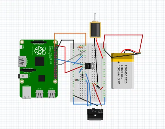
Key Components: Raspberry Pi GPIO, MOSFET, Relay, Resistors, and Diode
The circuit relies on several key components, each playing a vital role in ensuring proper functionality:
-
Raspberry Pi GPIO: The GPIO pin serves as the control signal for the MOSFET. It outputs a small voltage (typically 3.3V) to switch the MOSFET on or off. This allows the Raspberry Pi to control the relay without directly handling high currents.
-
MOSFET: The MOSFET acts as the main switching element in the circuit. It connects the relay to the ground when activated, completing the circuit and energizing the relay coil. Selecting the right MOSFET is crucial. It must have a low gate threshold voltage (Vgs) to operate effectively with the Raspberry Pi’s GPIO output. Additionally, it should handle the current required by the relay without overheating.
-
Relay: The relay is an electromechanical switch that allows the Raspberry Pi to control high-power devices. It requires a 5V input to activate its coil, which creates a magnetic field to close or open the switch. Matching the relay’s voltage and current requirements with the circuit’s design ensures reliable operation.
-
Resistors: Resistors R1 and R2 play critical roles in the circuit. R1 limits the current flowing into the MOSFET gate, preventing damage to the GPIO pin. R2 ensures the MOSFET turns off completely when the GPIO pin is low, avoiding unintended activation.
-
Diode: A flyback diode is placed across the relay coil to protect the circuit from back EMF. When the relay is deactivated, the collapsing magnetic field generates a voltage spike. The diode provides a path for this current, preventing damage to the MOSFET and other components.
By carefully selecting and integrating these components, the circuit achieves efficient and safe relay switching. Understanding how to switch a MOSFET to drive a 5V relay from Raspberry Pi requires attention to these details, ensuring the circuit operates as intended.
Drive a Relay with a MOSFET: Components and Selection
MOSFET: Purpose and Selection Criteria
The MOSFET serves as the primary switching element in the circuit. It connects the relay to the ground, allowing the relay coil to energize when activated. Selecting the right MOSFET is critical for reliable operation. The chosen MOSFET must have a low gate threshold voltage (Vgs) to ensure compatibility with the Raspberry Pi GPIO output, which typically operates at 3.3V. Additionally, the MOSFET should handle the current required by the relay without overheating or causing excessive power dissipation.
Experimental studies highlight the importance of considering parasitic parameters when selecting MOSFET models. For example, SiC MOSFETs, such as the SCH0280KE, exhibit fast switching speeds but are sensitive to parasitic inductances and capacitances. This sensitivity can lead to switching ringing, with current overshooting exceeding 100% and ringing frequencies in the MHz range. Designers must account for these factors to avoid performance issues in the circuit.
Resistors: Role and Choosing the Right Values
Resistors play a vital role in ensuring the MOSFET operates correctly. Resistor R1 limits the current flowing into the MOSFET gate, protecting the Raspberry Pi GPIO pin from damage. Resistor R2 ensures the MOSFET turns off completely when the GPIO pin is low, preventing unintended activation of the relay coil.
Choosing the right resistor values requires careful analysis. Statistical comparisons of resistor value choices in similar circuits provide valuable insights. The table below summarizes simulation results for resistor values:
|
Method |
Average |
Minimum |
Maximum |
Standard Deviation |
|---|---|---|---|---|
|
WCA |
3.30013 |
3.21051 |
3.39153 |
0.04684 |
|
Gaussian |
3.29944 |
3.24899 |
3.35720 |
0.01931 |
|
Monte Carlo |
3.29844 |
3.21955 |
3.36922 |
0.03293 |
These results demonstrate the importance of selecting resistor values that balance performance and reliability. Proper resistor selection ensures the circuit operates efficiently and protects the components.
Diode: Back EMF Protection and Selection
The diode is essential for protecting the circuit from back EMF generated by the relay coil. When the relay is deactivated, the collapsing magnetic field in the relay coil produces a voltage spike. This spike can damage the MOSFET and other components if not properly managed. The diode provides a path for this current, dissipating the stored energy safely.
Several studies discuss diode selection for back EMF protection. Key considerations include the use of Zener diodes or TVS diodes in conjunction with standard diodes. These components enhance the dissipation of stored energy in the relay coil, ensuring the circuit remains protected during operation. Proper diode selection minimizes the risk of damage and extends the lifespan of the circuit.
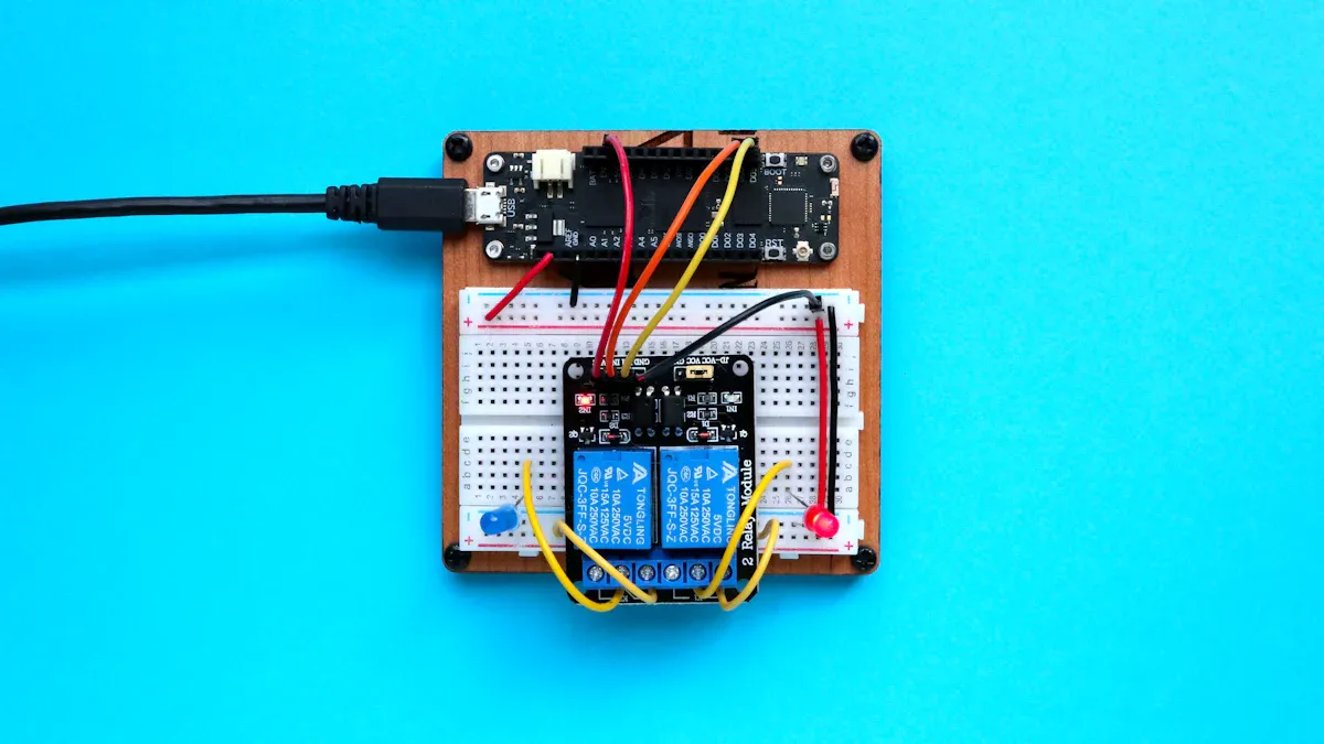
Relay: Function and Matching Voltage/Current Requirements
The relay acts as an electromechanical switch, allowing the Raspberry Pi to control high-power devices. The relay coil requires a specific voltage and current to activate, typically 5V for this application. Matching the relay’s voltage and current requirements with the circuit design ensures reliable operation.
Technical benchmarks provide insights into relay specifications. Important factors include coil voltage and current, contact ratings, and switching capacity. For example:
-
Coil Voltage and Current: The relay coil typically operates at 5V DC, with current requirements varying based on the relay model.
-
Contact Ratings: These ratings indicate the maximum voltage and current the relay contacts can handle, preventing damage to the load circuit.
-
Switching Capacity: This measures the maximum power the relay contacts can switch, ensuring compatibility with the load circuit.
Operational data further validates the relay’s performance. During testing, the relay successfully cleared a single line-to-ground fault event on phase B, located 14.37 miles from Substation A. The relay recorded four 16-cycle long events during the fault duration, confirming its effectiveness under specified voltage and current conditions.
By carefully selecting and integrating these components, the circuit achieves efficient and safe relay switching. Understanding the purpose and selection criteria for each component ensures the circuit operates as intended.
Circuit Assembly and Testing

Step-by-Step Wiring Instructions
Assembling the circuit requires careful attention to detail to ensure proper functionality. Follow these steps:
-
Soldering the Main Board: Place all internal components, including the MOSFET, relay, resistors, and diode, onto the main board. Arrange them compactly to fit within the enclosure. Ensure the terminal block faces outward for easy access.
-
Connecting the MOSFET: Attach the MOSFET’s gate to the Raspberry Pi GPIO pin through a resistor. Connect the source terminal to the ground and the drain terminal to the relay coil.
-
Adding the Flyback Diode: Position the diode across the relay coil terminals. This protects the circuit from kickback voltage when the relay deactivates.
-
Interface and Enclosure: Mount interface components, such as the toggle switch and battery connections, on the enclosure boundary. Ensure external accessibility for these components.
Testing the Circuit for Proper Functionality
Testing ensures the circuit operates as intended. Perform the following tests:
-
-
Conduct a continuity test to check for open circuits.
-
Perform an isolation test to verify resistance between connections.
-
-
Assembled Board Testing:
-
Use a continuity test to confirm proper connections.
-
Apply a hi-pot test to assess isolation between different nets.
-
Measure impedance using time-domain reflectometry (TDR) for single-ended and differential traces.
-
|
Testing Type |
Purpose |
|---|---|
|
Bare Board Testing |
Checks connectivity before component assembly. |
|
– Isolation Test |
Verifies resistance between electrical connections. |
|
– Continuity Test |
Checks for open circuits within the board. |
|
Assembled Board Testing |
Ensures integrity and functionality of the assembled components. |
Troubleshooting Common Issues
If the circuit does not function correctly, consider these troubleshooting tips:
-
Relay Not Activating: Verify the MOSFET gate voltage. Ensure it exceeds the MOSFET’s gate threshold voltage.
-
MOSFET Overheating: Check the current flowing through the relay coil. Ensure it does not exceed the MOSFET’s rated current.
-
Kickback Voltage Damage: Confirm the flyback diode is correctly installed across the relay coil. Replace it if damaged.
-
Open or Short Circuits: Use a continuity test to identify and fix any open or short circuits in the wiring.
By following these steps, the circuit can be assembled, tested, and troubleshooted effectively, ensuring reliable operation.
Driving a 5V relay with a MOSFET and Raspberry Pi offers a practical solution for controlling high-power devices. Selecting components carefully ensures the circuit operates reliably. Assembly and testing steps play a crucial role in achieving safe functionality. This method simplifies automation tasks while maintaining efficiency and protecting sensitive electronics.
How does a MOSFET act as a switch in this circuit?
A MOSFET as a switch connects the relay to the ground. It energizes the relay coil when activated by the Raspberry Pi GPIO pin.
Why is a flyback diode necessary for the relay?
The flyback diode protects the circuit from voltage spikes caused by the relay’s magnetic field collapse. It prevents damage to the MOSFET and other components.
Can this circuit handle high-power loads?
Yes, the relay can control high-power loads. The MOSFET ensures efficient switching, while the relay isolates the Raspberry Pi from high currents.
See Also
Exploring The IRF820 MOSFET For Power Management Applications
Guide To Using ATA5824C In Remote Control Applications
Step-By-Step Guide To Smart Home Automation With STM32F030C8T6
Enhancing Process Control By Utilizing AD74413RBCPZ Features
Integrating Bluetooth Control In Robots Using STM32F103C8T6