Switching a SIM800L modem without a relay is achievable by leveraging an ESP32 alongside a JT transistor and MOSFET supply circuit. This method removes the reliance on mechanical components, resulting in a more compact and robust setup. By integrating the GPIO pins of the ESP32 with a JT transistor and MOSFET supply, users can efficiently manage the modem’s power. This streamlined approach enhances the setup process while ensuring dependable performance. The SIM800L modem, combined with this configuration, serves as an ideal solution for IoT applications demanding reliable SIM communication.
Key Takeaways
-
Use an ESP32-CAM to control a SIM800L modem without a relay. This setup is small and works well for IoT projects.
-
Add a transistor and MOSFET circuit to control the modem’s power. This saves energy and makes it work better.
-
Make sure the ESP32-CAM and SIM800L get the right voltage. Use a voltage regulator to avoid damage from wrong voltage levels.
-
Test each part one by one before using the whole setup. This helps find problems and makes sure everything works well.
-
Use AT commands to check if the SIM800L is working. If it responds, the setup is working correctly.
Components for the Initial Setup

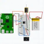
Building a functional circuit to switch the SIM800L GSM module using an ESP32 requires a few essential components. Each part plays a critical role in ensuring the system operates efficiently. Below is a breakdown of the key components needed for the initial setup.
ESP32-CAM Microcontroller
The ESP32-CAM serves as the brain of this setup. It is a compact and powerful microcontroller equipped with Wi-Fi and Bluetooth capabilities. Its GPIO pins allow users to control external devices, such as the SIM800L GSM module, with precision. The ESP32-CAM also features a built-in camera, making it ideal for IoT projects that require image capture or video streaming.
When integrating the ESP32-CAM into the circuit, ensure proper power supply and pin configuration. The microcontroller typically operates on 3.3V, so voltage regulation is crucial to prevent damage. Additionally, its small size makes it a perfect choice for compact setups where space is limited.
SIM800L GSM Module
The SIM800L GSM module is a versatile device that enables communication over GSM networks. It supports voice calls, SMS, and data transmission, making it a popular choice for IoT applications. This module requires a SIM card to connect to the GSM network and can operate on a wide range of voltages, typically between 3.4V and 4.4V.
To include the SIM800L GSM module in the initial setup, connect its power input to a stable voltage source. Use the ESP32-CAM’s GPIO pins to control the module’s operation via a transistor-based circuit. Proper wiring and voltage regulation are essential to ensure reliable performance. The module’s compact design and low power consumption make it ideal for portable and energy-efficient projects.
Tip: Always check the SIM card’s compatibility with the GSM network in your region before inserting it into the SIM800L GSM module.
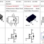
Transistors (e.g., NPN or MOSFET)
Transistors act as electronic switches in this setup. They enable the ESP32-CAM to control the power supplied to the SIM800L GSM module. NPN transistors and MOSFETs are commonly used for this purpose due to their efficiency and reliability.
In the circuit, the transistor connects the ESP32-CAM’s GPIO pin to the SIM800L GSM module. When the GPIO pin outputs a signal, the transistor allows current to flow, powering the module. Resistors are often added to the base or gate of the transistor to regulate the current and protect the components.
Choose a transistor that can handle the current requirements of the SIM800L GSM module. For most setups, a MOSFET with a low gate threshold voltage works well. Proper heat dissipation and wiring are also important to ensure the transistor operates safely.
Resistors for base/gate control
Resistors play a vital role in controlling the base or gate of transistors within the circuit. They regulate the current flowing into these components, ensuring stable operation and protecting them from damage. Without proper resistance, excessive current could flow through the transistor, potentially overheating or damaging it.
When designing the circuit for the SIM800L modem, selecting the right resistor value is essential. The resistor connected to the base of an NPN transistor or the gate of a MOSFET determines how much current flows through the transistor. For most setups, a resistor value between 1kΩ and 10kΩ works well. This range provides sufficient control while minimizing power loss.
Tip: Use a multimeter to measure the resistor’s value before adding it to the circuit. This ensures accuracy and prevents errors during the initial setup.
Resistors also help prevent unintended activation of the transistor. When the ESP32-CAM GPIO pin outputs a signal, the resistor ensures that the transistor switches on smoothly. This controlled activation is crucial for maintaining the reliability of the SIM800L modem’s operation.
Power supply (e.g., 5V or 3.7V battery)
A stable power supply is critical for the proper functioning of the ESP32-CAM and SIM800L modem. Both components require specific voltage levels to operate efficiently. The ESP32-CAM typically runs on 3.3V, while the SIM800L modem operates within a range of 3.4V to 4.4V.
For the initial setup, a 5V power source or a 3.7V lithium-ion battery can be used. If a 5V supply is chosen, a voltage regulator is necessary to step down the voltage for the ESP32-CAM. This prevents overvoltage, which could damage the microcontroller. Similarly, the SIM800L modem requires a stable voltage to avoid communication errors or unexpected shutdowns.
Note: Ensure the power supply can deliver sufficient current to both the ESP32-CAM and SIM800L modem. The SIM800L may draw higher currents during GSM communication, especially when transmitting data or making calls.
Using a battery provides portability, making the setup ideal for IoT applications in remote locations. However, monitoring the battery’s charge level is important to prevent interruptions in operation. For stationary setups, a regulated DC power adapter offers a reliable alternative.
Jumper wires and breadboard
Jumper wires and a breadboard simplify the process of connecting components during the initial setup. Jumper wires allow users to create temporary connections between the ESP32-CAM, SIM800L modem, transistors, and resistors. These wires come in various lengths and types, such as male-to-male, female-to-female, and male-to-female, providing flexibility in circuit design.
A breadboard serves as a platform for assembling the circuit without soldering. It features rows of interconnected holes that hold components securely. This makes it easy to test and modify the setup before finalizing the design. For beginners, using a breadboard reduces the risk of wiring errors and allows for quick adjustments.
Tip: Label the jumper wires or use color-coded wires to identify connections easily. This helps avoid confusion during testing and troubleshooting.
While jumper wires and breadboards are ideal for prototyping, transitioning to a soldered circuit on a PCB is recommended for long-term projects. This ensures durability and minimizes the chances of loose connections.
Circuit Design for SIM800L Switching
Transistor-based switching mechanism
A transistor-based switching mechanism forms the core of this design. Transistors act as electronic switches, enabling the ESP32 to control the power supplied to the SIM800L module. This approach eliminates the need for mechanical relays, making the setup more compact and reliable.
In this circuit, an NPN transistor or a MOSFET is used. When the ESP32 sends a signal through its GPIO pin, the transistor activates, allowing current to flow from the power source to the SIM800L module. This process ensures that the GSM module only receives power when needed, conserving energy and preventing unnecessary wear on the components.
The transistor’s base (or gate, in the case of a MOSFET) connects to the ESP32’s GPIO pin through a resistor. This resistor regulates the current entering the transistor, protecting it from damage. The collector (or drain) connects to the SIM800L module, while the emitter (or source) connects to the ground. This configuration ensures efficient switching and stable operation of the GSM module.
Tip: Choose a transistor with a low gate threshold voltage if using a MOSFET. This ensures compatibility with the ESP32’s GPIO output levels.
Connecting ESP32-CAM GPIO pins to the transistor
The ESP32-CAM’s GPIO pins play a crucial role in controlling the transistor. These pins output digital signals that determine whether the transistor is in an “on” or “off” state. Proper connection and configuration of these pins are essential for the reliable operation of the SIM800L module.
To connect the GPIO pin to the transistor, use a resistor with a value between 1kΩ and 10kΩ. This resistor limits the current flowing into the transistor’s base or gate, preventing damage to both the transistor and the ESP32. Attach one end of the resistor to the GPIO pin and the other end to the transistor’s base (or gate).
Next, connect the transistor’s emitter (or source) to the ground. The collector (or drain) connects to the SIM800L module’s power input. When the GPIO pin outputs a high signal, the transistor switches on, allowing current to flow to the GSM module. Conversely, when the GPIO pin outputs a low signal, the transistor switches off, cutting power to the module.
Note: Ensure the GPIO pin used for this connection is configured as an output in the ESP32’s code. This allows the pin to send the necessary signals to control the transistor.
Wiring the SIM800L modem to the transistor circuit
Proper wiring of the SIM800L modem to the transistor circuit ensures stable operation and reliable GSM communication. Begin by connecting the modem’s power input to the transistor’s collector (or drain). This connection allows the transistor to control the flow of current to the module.
The SIM800L modem also requires a stable voltage source. Connect the positive terminal of the power supply to the transistor’s collector (or drain) and the negative terminal to the ground. Use a voltage regulator if necessary to ensure the power supply matches the module’s voltage requirements, typically between 3.4V and 4.4V.
Additionally, connect the modem’s ground pin to the circuit’s common ground. This ensures a complete electrical path and prevents potential issues caused by floating grounds. Use jumper wires to make these connections on a breadboard for easy testing and adjustments.
Tip: Double-check all connections before powering the circuit. Incorrect wiring can damage the SIM800L module or other components.
The SIM800L modem’s communication pins, such as TX and RX, can also be connected to the ESP32 for data exchange. However, this step is optional for basic power switching and can be added later if needed.
Voltage regulation and power supply considerations
Voltage regulation plays a crucial role in ensuring the stable operation of the SIM800L module and ESP32-CAM. Both components require specific voltage levels to function correctly. The SIM800L module operates within a voltage range of 3.4V to 4.4V, while the ESP32-CAM typically runs on 3.3V. Supplying incorrect voltage can lead to malfunction or permanent damage.
Choosing the Right Voltage Regulator
A voltage regulator ensures that the power supply matches the required voltage levels for the components. For this setup, a Low Dropout Regulator (LDO) is ideal. It provides stable output voltage even when the input voltage is close to the desired output. For instance, an LDO can step down a 5V power source to 3.3V for the ESP32-CAM.
Tip: Select a voltage regulator with sufficient current capacity to handle the GSM module’s peak current demands during communication.
Managing Power Supply for GSM Communication
The SIM800L module draws higher currents during GSM operations, such as sending data or making calls. A power supply capable of delivering at least 2A is recommended. Insufficient current can cause the module to reset or lose connection.
To prevent voltage drops, use capacitors near the SIM800L module’s power input. These capacitors store energy and release it during high current demands, stabilizing the voltage. A combination of a 100µF electrolytic capacitor and a 0.1µF ceramic capacitor works well for this purpose.
Wiring Considerations
Proper wiring minimizes power loss and ensures efficient voltage regulation. Use short, thick wires for connections between the power supply, voltage regulator, and components. This reduces resistance and prevents voltage drops.
Note: Double-check the polarity of all connections. Reversing the polarity can damage the SIM800L module or ESP32-CAM.
Safety precautions for the SIM800L and ESP32-CAM
Safety precautions protect the components and ensure the reliability of the setup. The SIM800L module and ESP32-CAM are sensitive to voltage fluctuations, overheating, and incorrect wiring. Following these precautions minimizes risks and extends the lifespan of the components.
Preventing Overvoltage
Overvoltage can damage the SIM800L module and ESP32-CAM. Always use a voltage regulator to match the power supply to the components’ requirements. Avoid connecting the components directly to a power source without regulation.
Managing Heat Dissipation
The SIM800L module generates heat during GSM communication. Excessive heat can affect performance or damage the module. To manage heat, ensure proper ventilation around the module. If necessary, attach a small heatsink to the module’s surface.
Tip: Monitor the module’s temperature during operation. If it feels excessively hot, check the power supply and current draw.
Protecting GPIO Pins
The ESP32-CAM’s GPIO pins control the transistor in this setup. Incorrect wiring or excessive current can damage these pins. Use resistors to limit the current flowing into the pins. Ensure the pins are configured as outputs in the code to prevent unintended behavior.
Avoiding Short Circuits
Short circuits can occur due to loose connections or exposed wires. Use insulated jumper wires and secure all connections on the breadboard. For long-term setups, solder the components onto a PCB to reduce the risk of shorts.
Testing Before Full Operation
Before powering the entire setup, test each component individually. Verify the voltage levels, current draw, and wiring connections. Use a multimeter to check for continuity and ensure there are no shorts.
Note: Always disconnect the power supply before making adjustments to the circuit.
Code Implementation for ESP32-CAM
Setting up the Arduino IDE for ESP32-CAM
The Arduino IDE simplifies programming for the ESP32. Users must install the ESP32 board package to begin. Open the IDE and navigate to “File > Preferences.” Add the URL https://dl.espressif.com/dl/package_esp32_index.json in the “Additional Board Manager URLs” field. Next, go to “Tools > Board > Board Manager” and search for ESP32. Install the package.
After installation, select “ESP32-CAM” from the board list under “Tools > Board.” Configure the port by connecting the ESP32 to the computer via a USB-to-serial adapter. Choose the correct COM port under “Tools > Port.” This setup ensures the IDE recognizes the ESP32 for programming.
Writing code to control GPIO pins
Controlling GPIO pins involves sending initial setup commands to the ESP32. These pins manage external devices like the SIM800L module. Begin by defining the GPIO pin connected to the transistor. Use the pinMode() function to set the pin as an output.
For switching the SIM800L modem, use digital signals. The digitalWrite() function sends HIGH or LOW signals to the GPIO pin. HIGH activates the transistor, powering the module. LOW deactivates it, cutting power. These commands form the basis of Arduino-based GSM setups.
Example code for switching the SIM800L modem
Below is an example code snippet for switching the SIM800L modem using the ESP32:
#define SIM800L_PIN 4  // GPIO pin connected to the transistor

void setup() {
  pinMode(SIM800L_PIN, OUTPUT);  // Set GPIO pin as output
}

void loop() {
  digitalWrite(SIM800L_PIN, HIGH);  // Power on SIM800L module
  delay(5000);  // Keep module on for 5 seconds
  digitalWrite(SIM800L_PIN, LOW);  // Power off SIM800L module
  delay(5000);  // Keep module off for 5 seconds
}
This code alternates the power state of the SIM800L module every five seconds. Users can modify the delay values to suit their requirements. The commands ensure precise control over the module’s operation.
Explanation of code logic and GPIO configuration
The example code provided earlier demonstrates how the ESP32-CAM controls the SIM800L modem using its GPIO pins. Understanding the logic behind this code is essential for implementing and customizing the setup effectively.
Code Logic Breakdown
The code begins by defining the GPIO pin connected to the transistor. This pin acts as the control signal for switching the SIM800L modem on and off. The setup() function initializes the pin as an output using the pinMode() command. This configuration allows the ESP32-CAM to send digital signals to the transistor.
In the loop() function, the digitalWrite() command alternates the pin’s state between HIGH and LOW. When the pin is set to HIGH, the transistor activates, allowing current to flow to the SIM800L modem. This powers the modem and enables GSM communication. When the pin is set to LOW, the transistor deactivates, cutting off power to the modem. The delay() function introduces a pause between these states, ensuring the modem remains powered for a specific duration before switching off.
Tip: Adjust the delay values in the code to match the operational needs of your project. Longer delays keep the modem active for extended periods, while shorter delays conserve energy.
GPIO Configuration Details
The ESP32-CAM features multiple GPIO pins, each capable of sending digital signals. For this setup, a single GPIO pin connects to the transistor’s base or gate. This pin must be configured as an output to control the transistor effectively.
To avoid conflicts, users should verify that the chosen GPIO pin is not reserved for other functions, such as the camera module or serial communication. Pins like GPIO4 or GPIO5 are commonly used for external control circuits. Proper pin selection ensures reliable operation without interfering with other components.
Note: Refer to the ESP32-CAM pinout diagram to identify available GPIO pins and their functions.
The GPIO configuration in the code ensures smooth switching of the SIM800L modem. By understanding this setup, users can adapt the code for different GPIO pins or integrate additional components into their circuit.
Testing and Troubleshooting the GSM Setup
Testing the circuit functionality
Testing the circuit ensures that all components work as intended. Start by verifying the connections between the ESP32, the transistor, and the SIM800L module. Use a multimeter to check for continuity and confirm that no short circuits exist. Power the setup and observe the behavior of the SIM800L module. A steady red LED indicates that the module is receiving power correctly.
To test the switching mechanism, upload the example code to the ESP32. Monitor the GPIO pin’s output using an LED or an oscilloscope. The LED should blink in sync with the HIGH and LOW signals sent by the ESP32. If the SIM800L module powers on and off as expected, the circuit is functioning properly.
Tip: If the module does not respond, double-check the resistor values and ensure the GPIO pin is configured as an output in the code.
Verifying SIM800L modem operation
Once the circuit passes the initial test, verify the SIM800L modem’s operation. Insert a compatible SIM card into the module and connect its TX and RX pins to the ESP32. Open a serial monitor to send AT commands to the module. For example, send AT and expect an OK response. This confirms that the module is communicating with the ESP32.
Test the GSM functionality by sending SMS messages or making a call. Use the AT command AT+CMGS="phone_number" to send a message. Replace phone_number with the recipient’s number. After typing the message, press Ctrl+Z to send it. The module should respond with a message ID, indicating successful transmission.
Note: Ensure the SIM card has sufficient balance and is activated for GSM and GPRS services.
Addressing common issues (e.g., power supply, wiring errors)
Common issues can disrupt the setup’s functionality. Addressing these problems ensures reliable operation. Below are some frequent challenges and their solutions:
-
Power Supply Problems: The SIM800L module requires a stable power source. Insufficient current can cause the module to reset or fail during GSM communication. Use a power supply capable of delivering at least 2A. Add capacitors near the module to stabilize voltage during high current demands.
-
Wiring Errors: Incorrect connections often lead to non-functional circuits. Verify that the GPIO pin connects to the transistor’s base or gate through a resistor. Ensure the module’s ground pin is connected to the common ground.
-
Communication Failures: Users have reported issues such as garbage characters during data transmission or a flashing green LED on faulty modules. These problems often occur when using an external antenna. Test the setup without the antenna to isolate the issue.
-
Debugging Tips: If the module does not respond to AT commands, check the TX and RX connections. Swap the pins if necessary, as incorrect wiring can prevent communication. Additionally, pressing the reset button on the ESP32 can help reinitialize the setup.
Tip: Use a regular Arduino UNO to test the SIM800L module if issues persist. Some users have found it more reliable for debugging.
Debugging ESP32-CAM and SIM800L communication
Debugging communication between the ESP32-CAM and the SIM800L modem requires a systematic approach. Identifying and resolving issues ensures reliable operation and smooth data exchange. Below are common problems and their solutions.
1. Checking TX and RX Connections
The TX (transmit) and RX (receive) pins form the backbone of communication between the ESP32-CAM and the SIM800L. Incorrect wiring often leads to communication failures. Verify that the TX pin of the ESP32 connects to the RX pin of the SIM800L and vice versa. Swapping these connections can resolve many issues.
Tip: Use jumper wires with secure connections to avoid loose or intermittent signals.
2. Ensuring Proper Baud Rate
The baud rate mismatch is a frequent cause of communication errors. The SIM800L typically operates at a default baud rate of 9600. Ensure the ESP32-CAM’s serial communication settings match this value. Use the following code snippet to set the baud rate:
Serial.begin(9600); // Initialize serial communication at 9600 baud
If the module does not respond, try other common baud rates like 115200.
3. Testing with AT Commands
AT commands help verify the SIM800L’s functionality. Open the serial monitor in the Arduino IDE and send the AT command. A response of OK confirms proper communication. If no response appears, check the power supply and wiring.
Note: Ensure the serial monitor’s baud rate matches the one set in the code.
4. Resolving Power Supply Issues
Voltage drops during GSM operations can disrupt communication. Use capacitors near the SIM800L to stabilize the voltage. A 100µF electrolytic capacitor combined with a 0.1µF ceramic capacitor works effectively.
5. Monitoring Error Messages
Error messages provide valuable clues. For example, a +CME ERROR indicates a configuration issue. Refer to the SIM800L’s datasheet for error code explanations and corrective actions.
By following these steps, users can troubleshoot and resolve communication issues efficiently.
Switching a SIM800L modem using an ESP32-CAM offers a practical solution for IoT projects. The transistor-based circuit eliminates the need for relays, creating a compact and reliable setup. This approach leverages the ESP32’s GPIO pins to control the modem’s power efficiently. Users can integrate the SIM800L into their designs to enable GSM communication without mechanical components. This setup encourages experimentation and opens opportunities for further optimizations in IoT applications.
FAQ
What is the purpose of using a transistor instead of a relay?
A transistor replaces a relay to make the circuit more compact and reliable. It eliminates mechanical components, reducing wear and tear. This approach also allows faster switching and better integration with the ESP32-CAM’s GPIO pins.
Can the SIM800L module operate directly on a 5V power supply?
No, the SIM800L module requires a voltage range of 3.4V to 4.4V. A voltage regulator is necessary to step down a 5V power supply to the appropriate level. Supplying 5V directly can damage the module.
How can users ensure stable power for the SIM800L module?
Users should use a power supply capable of delivering at least 2A. Adding capacitors near the module’s power input helps stabilize voltage during high current demands, especially during GSM communication.
What precautions should be taken when wiring the SIM800L module?
Ensure proper polarity for all connections. Use short, thick wires to minimize resistance. Double-check the connections for the TX, RX, and power pins to avoid communication or power issues.
Is it necessary to connect the SIM800L module’s TX and RX pins to the ESP32-CAM?
No, it is not mandatory for basic power switching. However, connecting these pins enables data exchange, allowing users to send AT commands and utilize GSM communication features.
See Also
A Comprehensive Guide to Smart Home Automation with STM32F030C8T6
Guide to Integrating ATA5824C in Remote Control Applications
Using STM32F103C8T6 for Bluetooth Control in Robotics
Simple Networking Solutions with XILINX XC7K325T-2FFG676C
Three Effective Methods for Integrating MC9S12XET512VAG