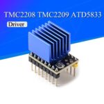
Precise motion control stands at the heart of robotics and modern motion control solutions. The TMC4671 and TMC6100 bring advanced motion control technology to systems that demand real-time motor control and high reliability. These modules deliver faster response and improved safety for motion systems. In comparison to standard controllers, TMC4671 and TMC6100 excel in control-loop frequency, stability, and safety features. The table below highlights key performance differences:
|
Feature / Metric |
TMC4671 / TMC6100 |
Standard Motion Controllers |
|---|---|---|
|
Control-loop frequency |
100 kHz (TMC4671) |
~20 kHz |
|
Frequency improvement factor |
5 times higher |
Baseline |
|
Resulting benefits |
Faster settling, better stability, lower overcurrent risk |
Slower response, less stability |
|
CPU resource requirement |
Offloads FOC from host |
Requires more CPU power |
|
Software complexity |
Reduced |
Higher |
|
Drive current and safety features |
Up to 1.5 A (TMC6100-LA-T), programmable safety |
Less integrated features |
Engineers choose TMC4671 and TMC6100 to achieve smooth motion and robust control in robotics and other systems.
Key Takeaways
-
Use the TMC4671 and TMC6100 together to achieve fast, stable, and safe motor control in robotics.
-
Set up hardware carefully by choosing the right components, wiring properly, and managing power to ensure reliable operation.
-
Install the correct firmware and use TMCL-IDE software to configure and test the controller for smooth communication and control.
-
Enter accurate motor and encoder parameters to enable precise feedback and motion control.
-
Tune PID and current loops carefully to improve motion accuracy, stability, and efficiency, and verify performance with test routines.
Hardware Setup

Components and Tools
Selecting the right components and tools ensures reliable performance from servo drive modules. The TMC4671 and TMC6100 work together to create powerful servo drives for robotics and automation. The TMC4671+TMC6100-TOSV-REF board operates as a BLDC servo driver from 12V to 36V and supports up to 6A RMS. This setup fits applications like medical ventilators and high-speed robotics. The TMC4671 servo controller IC runs a 100kHz PWM frequency, which reduces system current consumption by up to 15% compared to lower frequencies.
Essential components and tools include:
-
TMC4671 and TMC6100 evaluation boards
-
BLDC or servo motor
-
Power supply (12V–36V, rated for required current)
-
Connectors and wiring harnesses
-
Sensors (Hall, pressure, or encoder)
-
Raspberry Pi or similar interface (optional)
-
Multimeter and oscilloscope for testing
Open-source hardware and software support easy integration with sensors and user interfaces, making these servo motor drives suitable for many robotics projects.
Wiring tmc4671 and tmc6100
Proper wiring is critical for stable and efficient operation of servo drives. Ceramic capacitors should sit close to the MOSFETs to ensure low ESR decoupling. Electrolytic capacitors help dampen Vbus rail ringing. A 4-layer PCB with solid ground and power planes under the FETs reduces parasitic inductance. High current traces and gate drive loops must remain short and compact. These wiring standards, proven in similar drives, improve performance and reliability in robotics.
Tip: Always double-check connections before powering the system to prevent damage to the drive or motor.
Power and Safety
Safe operation of powerful servo drives depends on careful power management and safety checks. System testing validates safety and performance by measuring parameters like motion travel, velocity, and acceleration. Instruments such as laser interferometers and temperature sensors help monitor accuracy and thermal stability. Compliance with IEC 61508 functional safety standards ensures reliability. High-performance supervisory circuits, including power-supply monitors and watchdog timers, protect the system. Reliability is measured through metrics like mean time between failure and life tests under extreme conditions.
Note: Regularly inspect all connections and monitor system temperature during operation to maintain safe and reliable performance.
Firmware Setup
Firmware Selection
Selecting the right firmware is the first step in setting up the TMC4671 and TMC6100. Each controller requires firmware that matches the hardware version and the intended application. Most users download the latest firmware from the official Trinamic website. The firmware package usually includes files for both the servo controller and the gate driver. Users should check the documentation for compatibility with their evaluation board. After downloading, they transfer the firmware to the controller using a USB or UART interface. This process ensures the hardware can support advanced motion control solutions.
Tip: Always verify the firmware version before installation. Using the correct version prevents compatibility issues and supports stable operation.
Software Connection
After installing the firmware, users connect the controller to a PC for configuration. TMCL-IDE is a popular tool for this purpose. It provides a graphical interface for programming and tuning. Users connect the evaluation board to the computer with a USB cable. TMCL-IDE detects the controller and displays its status. The software allows users to set motor parameters, adjust control loops, and monitor real-time data. This step prepares the system for precise motion control.
Communication Test
Testing communication ensures the controller responds to commands. Users open TMCL-IDE and send a simple command, such as reading the firmware version. The controller should reply with the correct information. If no response appears, users check the cable connections and power supply. They may also review the COM port settings in the software. A successful test confirms that the programming environment and hardware communicate correctly.
Note: If problems persist, users can consult the troubleshooting section in the documentation or seek help from online forums.
Basic Control
Motor Parameters
Setting the correct motor parameters forms the foundation of precise motion control. The TMC4671 and TMC6100 work together as a single-axis servo controller to drive motors in robotics and automation systems. Users must enter the motor type, number of pole pairs, rated current, and maximum speed into the controller software. These values help the controller generate the right signals for the motor.
A typical setup process includes:
-
Identifying the motor type (BLDC, PMSM, or stepper).
-
Entering the number of pole pairs, which affects how the controller synchronizes with the motor.
-
Setting the rated current to protect the motor and ensure efficient operation.
-
Defining the maximum speed and torque limits for safe motion.
Tip: Always check the motor datasheet for accurate parameters. Incorrect values can lead to unstable motion or reduced performance.
Correct motor parameters allow the servo system to deliver smooth velocity and precise torque. This step ensures the system responds accurately to control commands.
Encoder Setup
Encoders provide essential feedback for closed-loop control. The TMC4671 supports various encoder types, such as incremental, Hall, and absolute encoders. Users must select the encoder type in the software and enter the resolution, which is the number of counts per revolution.
The setup process involves:
-
Connecting the encoder wires to the controller.
-
Selecting the encoder type in the configuration menu.
-
Entering the encoder resolution.
-
Checking the direction of rotation to match the motor and encoder.
A table can help organize encoder settings:
|
Encoder Type |
Resolution (CPR) |
Wiring Required |
Typical Use Case |
|---|---|---|---|
|
Incremental |
1000–10000 |
A, B, Z |
Robotics, CNC |
|
Hall |
6 |
U, V, W |
BLDC commutation |
|
Absolute |
4096+ |
Data, Clock |
High-precision servo |
Accurate encoder setup ensures the controller receives reliable feedback. This feedback allows the system to maintain precise position and velocity during motion.
Motion Verification
After setting motor and encoder parameters, users must verify motion to confirm correct operation. The controller software provides tools to test basic motion commands. Users can command the servo to move to a specific position or run at a set speed.
A simple motion verification routine includes:
-
Sending a position or velocity command from the software.
-
Observing the motor response and checking for smooth motion.
-
Monitoring feedback systems to ensure the encoder reports correct position and speed.
-
Checking for any unusual noise or vibration, which may indicate incorrect setup.
Note: Always monitor system temperature and current during initial tests. Safe operation protects both the servo and the controller.
Successful motion verification proves that the system can execute precise movements. This step confirms that the control loops, feedback, and motor parameters work together for reliable motion in robotics and automation systems.
Tuning

Fine-tuning the TMC4671 and TMC6100 brings out the best performance in any robot or automation system. Careful adjustment of control parameters ensures smooth, accurate, and reliable motion. This section explains how to tune the PID controller, set up the current loop, and achieve precise position control.
PID Adjustment
PID (Proportional-Integral-Derivative) controllers play a key role in robot motion. They help the servo system respond quickly and accurately to commands. Engineers use performance data to select and adjust PID settings for optimal control. The tuning process often involves applying step inputs and measuring how the system responds.
-
Step response characteristics such as settling time and overshoot show how well the controller handles sudden changes.
-
Frequency response and repeatability measurements help evaluate the stability and accuracy of the PID loop.
-
Engineers use response surface methodology to find the best PID gains based on measured data.
-
Both manual and automated tuning rely on metrics like overshoot, settling time, and vibration tests.
-
Validation includes vibration analysis, repeatability tests, motion cycle time, throughput, and reliability checks.
-
Regular tuning keeps PID loops calibrated for stable and accurate robot motion.
-
Software tools and simulators can analyze frequency domain data and automate PID adjustments.
Tip: Start with conservative PID values and increase gains slowly. Watch for signs of instability, such as oscillation or excessive vibration.
A well-tuned PID controller allows the servo to follow commands with minimal error. This leads to smoother motion and better control in robotics applications.
Current Loop
The current loop forms the foundation of field-oriented control. It regulates the amount of current flowing through the motor windings. Accurate current control ensures the motor produces the right torque for every movement.
Engineers set the current loop parameters using the controller software. They monitor the actual current and compare it to the target value. The TMC4671 and TMC6100 use high-speed feedback to adjust the current in real time. This approach improves efficiency and reduces heat in the motor.
A stable current loop prevents sudden spikes and keeps the system safe. It also supports advanced features like field-oriented control and sensorless operation. Engineers often use an oscilloscope to check the current waveform and verify that the loop responds quickly to changes.
Note: Proper current loop tuning protects the motor and drive electronics. Always check the datasheet for recommended current limits.
Position Control
Precise position control is essential for robotics, CNC machines, and automation systems. The TMC4671 and TMC6100 support both absolute and incremental encoders for accurate feedback. Engineers configure the position loop in the controller software, setting parameters such as position gain and allowable error.
The position loop works together with the current and velocity loops. It ensures the motor moves to the correct location and holds its position under load. Field oriented control enhances this process by aligning the motor’s magnetic field with the desired direction of movement.
Engineers test position control by commanding the motor to move to specific points. They check for accuracy, repeatability, and smoothness. Reliable position control enables robots to perform complex tasks with confidence.
Tip: Use high-resolution encoders for applications that require very fine position accuracy.
Testing and Troubleshooting
Test Routines
Engineers use structured test routines to verify that motion control systems perform as expected. They often start with simple point-to-point moves, checking if the motor reaches each position accurately. Next, they run the motor at different speeds and observe the response. Repeatability tests involve moving the motor back and forth between random positions to ensure the system returns to the same spot every time. These routines help identify any lost motion or inconsistencies. For more advanced checks, engineers may use step response tests to see how quickly the system reacts to sudden changes. They also monitor for smooth motion and listen for unusual sounds, which can signal mechanical or control issues.
Tip: Always record test results and compare them over time. This practice helps track improvements and spot new problems early.
Diagnostics
The TMC6100 includes built-in diagnostics and protection features that safeguard the system. Engineers can monitor real-time data such as current, voltage, and temperature through the controller software. The drive will trigger protection modes if it detects overcurrent, overheating, or abnormal voltage. These features prevent damage to both the motor and the electronics. Diagnostic logs help engineers trace faults and understand why a protection event occurred. Using these tools, they can quickly pinpoint issues and restore normal operation. Regular diagnostics keep the motion system reliable and extend the life of the drives.
Common Issues
Robotics control systems often face challenges like vibration, resonance, and noise. Mechanical compliance and backlash can cause instability or oscillations during motion. Engineers address these problems by tuning control parameters, using high-resolution encoders, and improving mechanical stiffness. Sometimes, replacing geared motors with direct drive motors increases system stability. Environmental factors such as temperature changes or ground vibrations may also affect performance. Advanced control algorithms and improved communication protocols help maintain precise motion even in demanding conditions. Over time, hands-on troubleshooting and upgrades lead to better system performance and reliability.
Note: Diagnosing and resolving real-world problems is a key part of mastering motion control systems.
Engineers achieve precise motion in robotics by following careful installation and tuning steps for TMC4671 and TMC6100. These systems benefit from real-time monitoring and diagnostics, which help maintain performance and support troubleshooting. TMCL-IDE and evaluation boards allow users to log data and probe signals, making ongoing maintenance easier. Regular checks and updates keep motion systems reliable. Developers can explore advanced features or connect these drives with control platforms like ROS for even greater flexibility.
What types of motors work with TMC4671 and TMC6100?
These controllers support BLDC, PMSM, and stepper motors. Users can select the motor type in the setup software. The system provides flexible options for many robotics and automation projects.
How does the system achieve precise motion control?
The TMC4671 and TMC6100 use advanced algorithms and real-time feedback. The controllers adjust current and position loops quickly. This approach helps robots and machines achieve smooth and accurate motion.
Can users monitor system status during operation?
Yes. The controller software displays real-time data such as current, voltage, and temperature. Engineers can use these features to check system health and ensure safe operation.
What safety features protect the drive and motor?
The TMC6100 includes overcurrent, overtemperature, and undervoltage protection. These features help prevent damage to the drive and motor. The system will shut down or alert users if it detects unsafe conditions.
Is it possible to update firmware after installation?
Users can update firmware using the official software tools. The process involves connecting the controller to a PC and following step-by-step instructions. Firmware updates add new features and improve performance.
See Also
Steps To Incorporate AEAT-8800-Q24 For Superior Robotics
Harnessing AD74413RBCPZ To Improve Process Management
Three Best Methods To Connect MC9S12XET512VAG Effectively
Enhancing Automotive Performance Using NXP MC9S12XEP100 And MC9S12XS128
Comprehensive Guide To ADXL357BEZ For Motion Sensing And Stability


