Connecting a TP4056 battery charger to lithium-ion batteries involves linking the module’s input to a USB power source and attaching the battery to the designated terminals. Makers and engineers choose the TP4056 for its low cost and reliability in projects ranging from power banks to wearable gadgets. The global demand for lithium-ion batteries continues to rise due to several factors:
-
More consumers use smartphones, tablets, and IoT devices every year.
-
Advances in battery efficiency and energy density improve device performance.
-
Asia Pacific leads in manufacturing, with a strong presence of every major TP4056 IC supplier from China.
Anyone with basic tools can set up a TP4056 battery charger safely by following clear steps and using proper safety precautions.
Key Takeaways
-
The TP4056 charger safely charges single-cell lithium-ion batteries using a constant current and voltage method, protecting battery life.
-
Always connect the battery and power supply with correct polarity to avoid damage and overheating of the charger module.
-
Adjust the charging current by changing the resistor on the PROG pin to match your battery’s capacity for safe and efficient charging.
-
Use the onboard LED indicators to monitor charging status: red means charging, green means fully charged.
-
Follow safety practices like wearing protective gear, ensuring good ventilation, and never leaving batteries unattended while charging.
TP4056 Battery Charger Basics
What Is the TP4056?
The TP4056 is a specialized integrated circuit designed for charging single-cell lithium-ion batteries. Engineers and hobbyists use the TP4056 battery charger in many projects because it offers a simple and reliable way to manage battery charging. The TP4056 charger board uses a constant-current/constant-voltage (CC/CV) charging method, which helps protect the battery and extend its lifespan. This chip is widely available and supports charging currents up to 1A, making it suitable for a range of portable electronics.
Key Features and Benefits
The TP4056 battery charger stands out for its technical features and safety protections. It supports adjustable charging currents, typically set by changing the RPROG resistor. The charger operates within an input voltage range of 4.5V to 5.5V and charges batteries to a full voltage of 4.2V. The TP4056 charger board includes built-in overcharge and over-discharge protection, as well as thermal regulation to prevent overheating. LED indicators show charging status, with a red light during charging and a green light when the battery is fully charged.
|
Specification Aspect |
Details |
|---|---|
|
Charging Method |
Linear charge (1% accuracy) |
|
Charging Current |
Default 1A, adjustable from 50mA to 1000mA via resistor (RPROG) |
|
Input Voltage |
4.5V to 5.5V |
|
Full Charge Voltage |
4.2V |
|
LED Indicators |
Red: Charging, Green: Fully charged |
|
Charging Input Interface |
Micro USB |
|
Working Temperature |
-10°C to +85°C |
|
Polarity Reversal |
Not allowed |
|
Dimensions |
25mm x 19mm x 10mm |
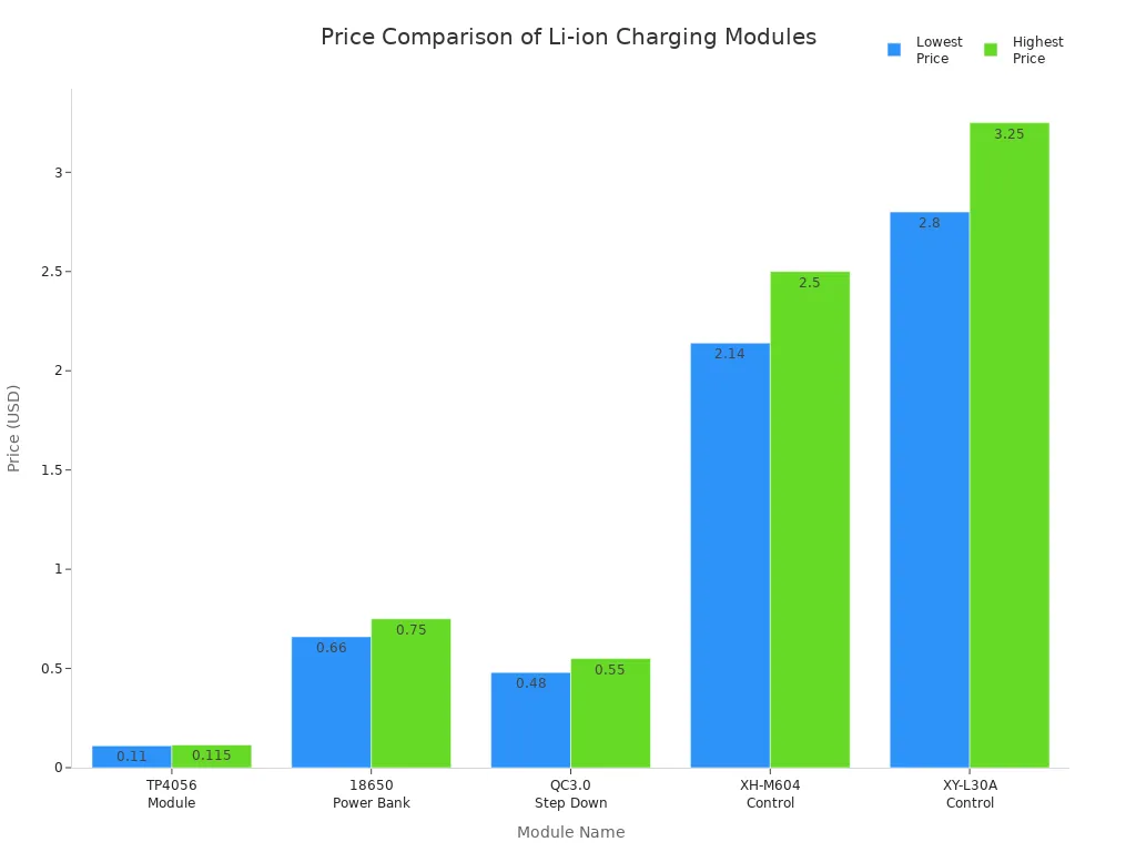
The TP4056 battery charger is also one of the most cost-effective solutions on the market. Its price is much lower than other lithium-ion charging modules, making it ideal for both DIY projects and mass production.
Common Applications
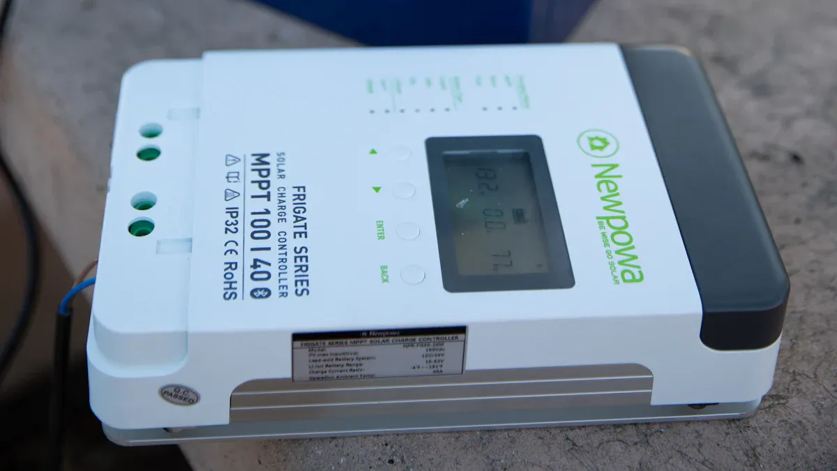
Many engineers and makers choose the TP4056 charger board for its versatility. The TP4056 battery charger powers portable power banks, wearable devices, and embedded systems. It is also popular in DIY electronics, solar-powered projects, and LED lighting. The TP4056 module helps maintain battery health and ensures safe charging in devices like smartwatches, fitness trackers, and IoT sensors. Its reliability and low cost make it a favorite for both small-scale and large-scale applications.
Materials and Setup
Required Components
Setting up a TP4056 charging circuit for single-cell lithium-ion batteries requires several essential parts. The TP4056 IC serves as the core, providing voltage and current regulation for safe charging. Most modules include a DW01A protection IC and dual MOSFETs, which help prevent overcharge, over-discharge, and short circuits. LEDs indicate the charging status, making it easy to monitor progress. A USB connector, such as Micro-USB or Type-C, supplies power to the module. Quality connectors link the battery to the BAT+ and BAT- terminals, minimizing resistance and ensuring a secure connection. A resistor, often 1kΩ, connects to the PROG pin to set the charging current. Some setups add capacitors for circuit stability and heat dissipation. Proper load connections allow devices to operate while the battery charges.
-
TP4056 IC (charging controller)
-
DW01A protection IC
-
Dual MOSFET (e.g., FS8205A)
-
Micro-USB or Type-C connector (power input)
-
LEDs (charging status indicators)
-
Connectors for battery terminals (BAT+ and BAT-)
-
Resistor for PROG pin (sets charging current)
-
Capacitors (for stability)
-
Quality wiring and heat dissipation materials
Choosing the Right Battery
Selecting a compatible battery ensures safe and efficient charging. The TP4056 module is designed for single-cell lithium-ion batteries with a nominal voltage of 3.7V. The charge voltage remains fixed at 4.2V, which matches the safety requirements for these batteries. The battery must handle a maximum charging current of 1A, as set by the module. High-quality connectors reduce resistance and improve performance. The battery should also tolerate the thermal conditions during charging.
|
Criteria |
Requirement/Specification |
|---|---|
|
Battery Type |
Single-cell lithium-ion batteries |
|
Nominal Voltage |
3.7V |
|
Charge Voltage |
4.2V (fixed) |
|
Maximum Charge Current |
Up to 1A |
|
Battery Current Rating |
≥1A |
|
Connection Quality |
High-quality connectors |
|
Thermal Considerations |
Must tolerate charging heat |
Safety Gear
Safety remains a top priority when working with lithium-ion batteries. Users should wear safety glasses to protect their eyes from accidental sparks. Insulated gloves help prevent electric shock. A fire-resistant mat or workspace reduces the risk of damage in case of a battery failure. Proper ventilation ensures that any fumes from a damaged battery dissipate quickly. Keeping a fire extinguisher nearby adds another layer of protection.
Tip: Always double-check battery polarity before connecting to the TP4056 module. Incorrect wiring can damage both the battery and the charger.
Wiring the TP4056
Power Input Connections
Connecting the power input to the TP4056 charger board is the first step in setting up a safe and efficient charging system. The module typically accepts power through a Micro-USB or USB-C connector. Most users choose a standard USB charger as the power source because it provides a stable 5V output. This voltage matches the recommended input range for the TP4056 charging module.
|
Parameter |
Recommended Range / Value |
|---|---|
|
Input Voltage Range |
4.5V to 5.5V |
|
Maximum Charge Current |
Up to 1A (adjustable) |
|
Recommended Power Source |
Stable 5V supply (e.g., USB charger) |
|
Notes |
Avoid exceeding 5.5V to prevent overheating; use regulators if input voltage is higher |
A stable 5V supply ensures the charger operates within safe limits. Supplying a voltage above 5.5V can cause the TP4056 charger board to overheat. Users should avoid connecting a 20V power supply directly, as this can damage the module and create a fire hazard. If the available power source exceeds 5.5V, a DC-DC converter or voltage regulator should be used to step down the voltage.
Tip: Always double-check the polarity of the power input. Reversing the positive and negative wires can cause the TP4056 module to overheat and damage internal components. Many users have reported fried modules due to swapped polarity.
Common wiring mistakes include:
-
Reversing the polarity of the power supply connection, which can damage the charger and cause overheating.
-
Using a power supply voltage higher than 5V, leading to excessive heat.
-
Failing to adjust the charge current resistor for the intended battery.
Battery Terminals
Properly connecting the battery to the TP4056 charger board is crucial for safe operation. The board features two clearly labeled pads: B+ and B-. The battery positive terminal connects to B+, and the negative terminal connects to B-. This direct connection allows the TP4056 to monitor and control the charging process.
-
Connect the battery positive terminal to the B+ pad on the TP4056 charger board.
-
Connect the battery negative terminal to the B- pad.
-
Double-check the polarity before powering the module. The TP4056 charging module does not have built-in reverse polarity protection.
-
For added safety, users can install external Schottky diodes between the charger, battery, and load. These diodes prevent reverse current flow and protect against accidental reverse polarity.
-
If the charger is unpowered, a diode between the charger and battery prevents the battery from driving current back into the charger.
Note: The DW01A protection IC on some TP4056 charger boards offers basic protection, but it does not guarantee safety against reverse polarity. Always verify connections before applying power.
Incorrect wiring of the battery terminals can permanently damage the TP4056 charger board. Users should disconnect the load during charging to avoid interference and ensure accurate charging.
Output Terminals
The output terminals on the TP4056 charger board allow the connected device to draw power from the battery while charging. These terminals are usually labeled OUT+ and OUT-. The output voltage and current characteristics match the requirements for most single-cell lithium-ion batteries, such as the popular 18650 cell.
|
Parameter |
Value |
|---|---|
|
Input Voltage |
4.5V to 6V (recommended 5V) |
|
Default Charging Current |
1A (adjustable via resistor R3) |
|
Charge Cut-off Voltage |
4.2V ± 1% |
|
Battery Overcharge Protection |
4.3V |
|
Battery Over-discharge Cutoff |
2.4V (disconnects battery output) |
|
Over-discharge Reconnect Voltage |
~2.9V |
|
Over-current Protection |
3A (disconnects output if exceeded) |
The TP4056 charger board uses a constant current/constant voltage (CC/CV) charging method. The output voltage is regulated to 4.2V during charging, and the default current is 1A, which can be adjusted by changing the programming resistor. These features ensure the battery charges safely and efficiently.
Callout: When connecting a load to the output terminals, ensure the total current draw does not exceed the protection limits of the TP4056 charger board. Drawing too much current can trigger the over-current protection and disconnect the output.
The output terminals provide a reliable interface for powering devices such as LED lights, IoT sensors, or portable electronics. The TP4056 charging module maintains battery health by preventing overcharge, over-discharge, and over-current conditions.
Configuring the TP4056 Charging Module
Adjusting Charging Current
The TP4056 charging module allows users to set the charging current to match the battery’s capacity. This adjustment ensures safe and efficient charging for different lithium-ion cells. The charging current is determined by the resistor connected from the PROG pin to ground. By changing this resistor, users can program the constant current level for the charging process. The maximum charging current for the TP4056 charging module is 1000mA (1A). Selecting a higher resistor value lowers the charging current, which helps protect smaller batteries from overheating or damage.
For batteries with higher capacities, a lower resistance value on the PROG pin increases the charging current. When charging at 700mA or above, a heat dissipation resistor between 0.2Ω and 0.5Ω is recommended. This setup prevents the TP4056 charging module from overheating during operation. Users can also connect multiple TP4056 charging modules in parallel to charge larger batteries, but they must ensure proper battery management and safety systems.
Tip: Always match the charging current to the battery’s specifications. Charging at a rate too high for the battery can reduce its lifespan or cause safety issues.
|
Battery Capacity (mAh) |
Recommended Charging Current (mA) |
PROG Resistor Value (kΩ) |
|---|---|---|
|
500 |
250 |
4.7 |
|
1000 |
500 |
2.2 |
|
2000 |
1000 |
1.0 |
Monitoring LEDs
The TP4056 charging module features onboard LEDs that provide clear feedback about the charging status. These indicators help users monitor the charging process without extra equipment.
-
The blue LED turns on when the battery is fully charged.
-
Charging begins automatically when the battery voltage drops below 4.2V.
-
The LEDs change color or turn off to signal the end of charging.
The TP4056 charging module does not use LED indicators for error conditions. Users should rely on the LEDs to confirm that charging is in progress or complete. If neither LED lights up, users should check the power supply and connections.
Note: Always observe the LED indicators during charging. If the red LED stays on for an unusually long time, the battery may have a problem or the charging current may be set too low.
Charging Best Practices
Following best practices with the TP4056 charging module helps maximize battery lifespan and ensures safe operation. The module uses a constant current/constant voltage (CC/CV) charging method, which protects the battery and improves efficiency. Built-in thermal regulation adjusts the charging current if the module gets too hot, preventing overheating.
Key best practices include:
-
Connect the battery to the B+ and B- terminals and the power source to IN+ and IN-, always checking polarity.
-
Set the correct charging current by calculating and installing the appropriate resistor on the PROG pin.
-
Monitor the charging process using the onboard LEDs to track progress and completion.
-
Use the TP4056 charging module within its specified input voltage range of 4.5V to 5.5V.
-
Disconnect the power source after charging to prevent unnecessary trickle charging, even though the module has overcharge protection.
-
Avoid discharging lithium-ion batteries below 3V per cell to maintain battery health.
-
Store batteries at 40-60% charge in a cool, dry place if not used for long periods.
-
Ensure proper heat dissipation and ventilation around the TP4056 charging module, especially when charging at higher currents.
-
Allow the battery to cool after charging before using or handling it.
🔋 Callout: Always verify all electrical connections before starting the charging process. Loose contacts or short circuits can damage the lithium battery charging module and the battery itself.
By following these guidelines, users can safely and effectively use the TP4056 charging module for charging batteries in a wide range of applications.
Safety and Troubleshooting
Battery Compatibility
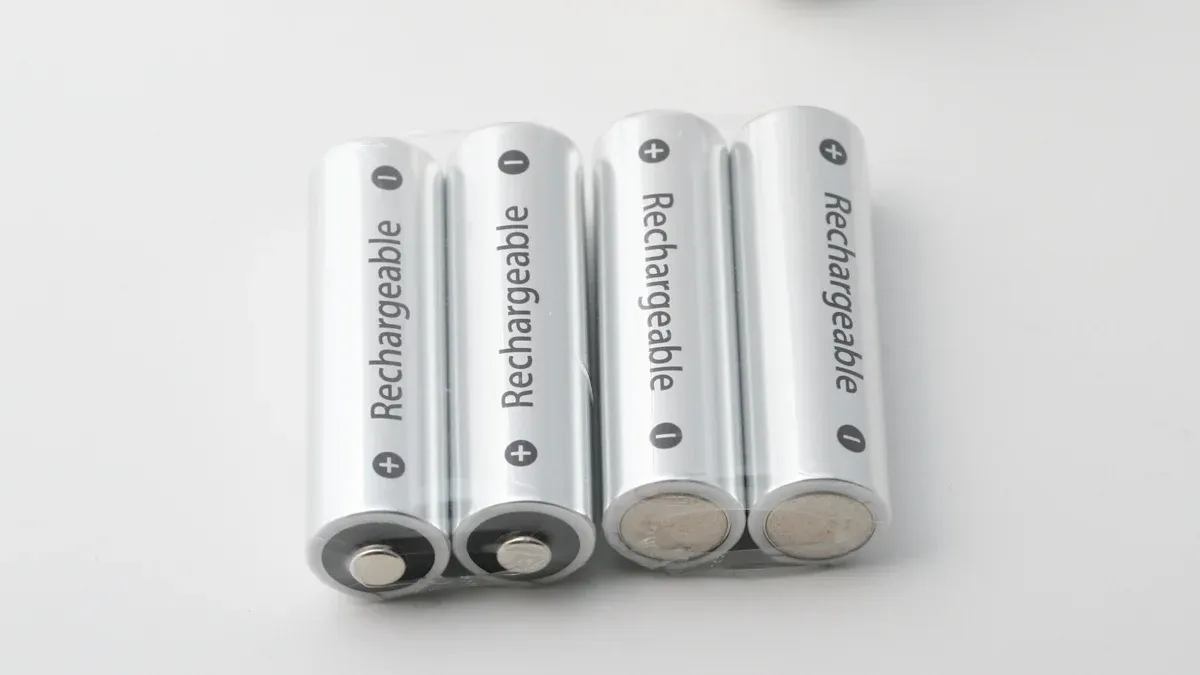
The TP4056 module works best with specific types of lithium-ion batteries. It uses a constant current/constant voltage charging method set at 4.2V, which matches the needs of single-cell lithium-ion batteries. Users often select the 18650 battery for projects, but any single-cell lithium-ion battery with a 3.7V nominal voltage fits this charging profile. The module does not support multi-cell batteries or other chemistries. Using the correct battery ensures reliable charging and activates built-in overcharge protection features.
-
Single-cell lithium-ion batteries (3.7V nominal, 4.2V full charge)
-
18650 batteries (common in DIY and portable devices)
-
Batteries used in IoT, prototyping, and educational projects
⚡ Tip: Always check the battery label and specifications before connecting it to the TP4056 module. This step helps prevent damage and ensures overcharge protection works as intended.
Overheating Issues
Overheating can occur during charging if users do not follow proper guidelines. Several factors contribute to excess heat:
-
Charging current above 1000mA stresses the chip and battery.
-
Poor heat dissipation from the PCB, such as limited copper area or missing heat sinks.
-
Improper soldering of the heat sink reduces cooling efficiency.
-
Reverse battery connection may cause chip burnout and overheating.
-
High ambient temperatures or operating outside the -40°C to 85°C range increase risk.
-
Charging at 700mA or higher requires extra heat dissipation, like resistors between 0.2Ω and 0.5Ω.
To prevent overheating, users should set the correct charging current, ensure good ventilation, and use a regulated power supply. Monitoring the battery temperature during charging helps maintain safety. Overcharge protection in the TP4056 module also helps prevent dangerous temperature rises.
🛡️ Note: Never leave a charging battery unattended. If the battery feels hot, stop charging and check the setup.
LED and Charging Problems
LED indicators on the TP4056 module provide feedback during charging. If the LEDs do not behave as expected, users can follow this troubleshooting table:
|
Issue Observed |
Possible Cause |
Solution |
|---|---|---|
|
Both LEDs flashing or lit |
No battery connected or testing with a capacitor |
Connect a real battery for accurate LED behavior |
|
LEDs do not light up |
Incorrect wiring or fake chip |
Check all connections and use authentic modules |
|
Red LED stays on too long |
Low charging current or degraded battery |
Adjust current setting or replace battery |
|
LED flickers when hand is near IC |
Environmental interference or grounding issue |
Improve grounding and reduce interference |
Other common charging problems include slow charging, interruptions, or batteries not holding charge. Users should check for secure connections, use high-quality power sources, and replace old batteries. Adjusting the programming resistor helps set the correct charging current. The TP4056 module’s overcharge protection and proper setup ensure safe and reliable operation.
Setting up a TP4056 battery charger involves connecting the power input, wiring the battery terminals, and adjusting the charging current for the battery type. Safety, correct wiring, and proper current selection remain essential for reliable operation. Makers can use the TP4056 in advanced projects, including embedded systems and portable electronics.
📚 For advanced configurations, always consult the TP4056 datasheet. The datasheet explains pin functions, resistor values, and temperature monitoring for safe charging. Trusted tutorials like Cirkit Designer and MYTECTUTOR offer step-by-step guidance and troubleshooting tips.
How can someone tell if the TP4056 module is charging a battery?
The red LED lights up when charging begins. The green LED turns on when the battery reaches full charge. Users should watch these indicators to track progress.
Can the TP4056 charge batteries with different capacities?
Yes. The TP4056 can charge single-cell lithium-ion batteries with various capacities. Users must set the correct charging current by adjusting the PROG resistor to match the battery’s rating.
Is it safe to leave a battery connected to the TP4056 overnight?
🔒 Tip: The TP4056 includes overcharge protection. However, users should avoid leaving batteries unattended during charging. Monitoring the process helps prevent accidents.
What happens if someone connects the battery with reversed polarity?
Reversed polarity can damage the TP4056 module and the battery. Users should always double-check connections before applying power.
Can the TP4056 module charge other battery types, like LiFePO4 or NiMH?
The TP4056 is designed for single-cell lithium-ion batteries only. It does not support LiFePO4, NiMH, or multi-cell packs. Using the wrong battery type may cause safety issues.
See Also
Steps To Boost Robotics Using AEAT-8800-Q24 Integration
Exploring LPQ252-CEF For Optimized Power Management Solutions
A Simple Guide To Integrate Sensors With SN74LVC4245APW
How To Use STM32F103C8T6 For Bluetooth Robot Control
Leveraging AD74413RBCPZ To Improve Process Control Efficiency