Reliable power management forms the backbone of any successful prototype. The TPS3809K33DBVR plays a critical role in this process by monitoring voltage levels and generating reset signals when necessary. This ensures that systems operate within safe voltage ranges, preventing malfunctions or data loss. In consumer electronics, this component proves invaluable for maintaining stability in devices like microcontroller-based systems and battery-powered gadgets. Its ability to safeguard against power-related issues makes it an essential tool for achieving dependable performance in prototypes.
Key Takeaways
-
The TPS3809K33DBVR checks voltage levels and sends reset signals. This helps devices work reliably in consumer electronics.
-
It uses little power and is small, making it great for battery devices and tight spaces.
-
To use it right, check voltage limits and match it with other parts to prevent problems.
-
Testing is important; watch the input voltage and reset actions to keep it working well during testing.
-
Design your PCB carefully to reduce noise and problems, making your prototype more reliable.
Understanding the TPS3809K33DBVR
Key Features of the TPS3809K33DBVR
Voltage monitoring and reset output
The TPS3809K33DBVR excels in voltage monitoring and reset functionality. It continuously tracks power supply levels and generates a reset signal when the voltage falls below a predefined threshold. This ensures that sensitive components in the circuit remain protected from low voltage conditions. Its active low threshold voltage detector with hysteresis enhances reliability by preventing erratic reset behavior during minor voltage fluctuations.
Low power consumption and compact design
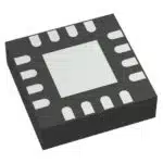
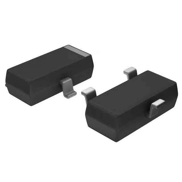
This IC is designed with efficiency in mind. Its low power consumption makes it ideal for battery-powered devices and portable electronics. The compact SOT-23-3 package simplifies integration into PCB designs, saving space in prototypes and enabling sleek, lightweight product designs.
Wide operating temperature range
The TPS3809K33DBVR operates reliably across a wide temperature range of -40 to 85 degrees Celsius. This feature ensures consistent performance in diverse environments, from industrial settings to consumer electronics. Its robust design supports applications requiring stability under varying conditions.
Applications in Consumer Electronics Projects
Power supply monitoring and reset
The TPS3809K33DBVR plays a vital role in monitoring power supply voltages. It ensures proper operation during power fluctuations by generating reset signals. This functionality is crucial for maintaining system stability in consumer electronics projects.
Microcontroller-based systems
In microcontroller-based systems, this IC ensures the microcontroller operates only within safe voltage ranges. It prevents malfunctions by providing a reset signal during power-up or when voltage levels drop unexpectedly.
Battery-powered devices and portable electronics
The TPS3809K33DBVR is ideal for portable electronics and battery-powered devices. It helps prevent unpredictable behavior by ensuring the system operates only when the battery voltage is sufficient. This feature is essential for maintaining reliability in devices like wearables and handheld gadgets.
Why It’s Essential for Prototyping
Ensuring system reliability
Prototyping new electronic hardware products requires components that guarantee reliability. The TPS3809K33DBVR ensures system stability by monitoring voltage levels and triggering resets when necessary. This functionality protects sensitive components and ensures proper operation after power-up or recovery from a reset condition.
Preventing power-related failures
This IC prevents power-related failures by accurately monitoring voltage thresholds. Its reset functionality safeguards the circuit from brown-out conditions, ensuring prototypes perform as expected during development and testing phases.
How to Integrate the TPS3809K33DBVR into a Prototype
Reviewing the Datasheet
Understanding pin configuration and functionality
The datasheet of the TPS3809K33DBVR serves as a comprehensive guide for understanding its pin configuration and functionality. This IC features three pins: VDD, GND, and RESET. The VDD pin connects to the power supply, while the GND pin ensures proper grounding. The RESET pin outputs a signal when the monitored voltage falls below the threshold. Engineers must carefully study the datasheet to ensure correct connections and avoid errors in the circuit diagram.
Analyzing electrical characteristics and thresholds
The datasheet provides critical details about the IC’s electrical characteristics, including voltage thresholds and current consumption. The TPS3809K33DBVR operates with a CMOS design, ensuring low power consumption. It monitors supply voltages with high accuracy, making it suitable for various applications. Designers should analyze these parameters to match the IC’s functionality with the prototype’s requirements. Following best practices in circuit design ensures optimal performance.
Designing the Schematic
Connecting the TPS3809K33DBVR to the power supply
When designing the schematic, connecting the TPS3809K33DBVR to the power supply is a crucial step. The VDD pin should link to the supply voltage, while the GND pin connects to the circuit’s ground. Passive components like capacitors and resistors stabilize the IC’s operation. A pull-up resistor on the RESET pin ensures a stable output signal.
Configuring the reset output for stability
Configuring the RESET pin is essential for maintaining stability in the circuit. Adding a capacitor to the RESET pin filters noise and debounces the signal. This configuration prevents false triggers and ensures reliable reset functionality. Proper power-on reset sequencing avoids missed resets during power-up.
PCB Layout Best Practices
Optimizing component placement
Optimizing component placement is vital when designing printed circuit boards. The TPS3809K33DBVR should be placed close to the power supply to minimize trace lengths. Short traces reduce signal degradation and improve the IC’s performance.
Minimizing noise and interference
Minimizing noise and interference enhances the reliability of the prototype. Designers should keep the RESET pin away from noisy traces to avoid false triggers. Adding a capacitor at the RESET pin further reduces noise. Following these practices ensures a clean and stable output signal.
Tip: Order PCB prototypes early to test the layout and refine the design before finalizing the circuit.
Testing and Validation
Verifying voltage thresholds and reset behavior
Testing the voltage thresholds and reset behavior ensures the TPS3809K33DBVR functions correctly in a prototype. Engineers should verify that the input voltage remains between 1.0V and 6V to avoid erratic IC performance. Monitoring the voltage at the input pin with an oscilloscope or voltmeter helps detect fluctuations that could disrupt the circuit. Proper grounding is essential to prevent erroneous readings.
The reset pin’s behavior must also be evaluated. If the reset pin appears stuck low or floating, it may cause unexpected resets. Debugging the reset threshold configuration ensures the IC triggers resets at the correct voltage levels. This step prevents premature or missed resets, which could compromise the circuit’s reliability. Additionally, the watchdog timer should be assessed to confirm it is configured correctly, avoiding unnecessary resets during operation.
External components like resistors and capacitors play a critical role in supporting the IC’s functionality. Engineers must confirm these components match the design requirements outlined in the circuit diagram. Proper selection of these passive components ensures the IC operates as intended, maintaining the stability of the prototype.
Ensuring compatibility with other components
Compatibility between the TPS3809K33DBVR and other components in the circuit is vital for successful prototyping. Designers should confirm that the IC’s voltage thresholds align with the power supply levels of the prototype. Mismatched voltage levels can lead to conflicts in circuit operation.
The reset output must integrate seamlessly with the microcontroller or other connected devices. Testing the output signal ensures it meets the timing and voltage requirements of the application. Engineers should also evaluate the BOM (bill of materials) to verify that all components, including the IC, are suitable for the design.
Noise and interference can affect the IC’s performance. Placing the IC close to the power supply and using capacitors to filter noise at the reset pin minimizes these issues. Testing the PCB layout for noise reduction ensures the circuit operates reliably. By following these steps, engineers can develop and prototype a stable new electronic hardware product.
Tip: Order PCB prototypes early to test the design printed circuit board and refine the layout before generating the final bill of materials.
Practical Tips for Using the TPS3809K33DBVR in Projects
Selecting the Right Variant for Your Prototype
Choosing appropriate voltage thresholds
Selecting the correct voltage thresholds ensures the IC operates effectively in the prototype. Designers must evaluate the power supply levels and determine the appropriate threshold for the application. For instance, a microcontroller-based circuit may require a threshold that aligns with the microcontroller’s operating voltage. External components like resistors and capacitors also influence the IC’s performance. Proper selection of these components ensures accurate voltage monitoring and reset functionality. Adding a delay capacitor can help manage reset timing and avoid power-on reset issues.
Considering package type and size
The TPS3809K33DBVR comes in a compact SOT-23-3 package, making it suitable for space-constrained designs. Engineers should consider the prototype’s size requirements and PCB layout when selecting the package. Compact designs benefit from the small footprint of this IC, while larger projects may prioritize ease of handling during assembly. The package type also affects thermal performance, which is critical for maintaining reliability in varying environments.
Ensuring Compatibility with System Design
Matching voltage levels with other components
Compatibility between the IC and other components ensures seamless operation. Designers must match the IC’s voltage thresholds with the power supply levels of the circuit. Passive components like resistors and capacitors play a crucial role in stabilizing the IC’s output. A pull-up resistor (10kΩ to 100kΩ) stabilizes the reset pin, while a capacitor (0.1 µF to 1 µF) filters noise and debounces the reset signal. Proper power-up timing ensures the IC triggers resets at the correct voltage levels.
Avoiding conflicts in circuit design
Engineers must avoid conflicts in the circuit design by maintaining signal integrity. Keeping the reset pin away from noisy traces minimizes interference. Short trace lengths reduce signal degradation, ensuring reliable output. Proper grounding and decoupling techniques further enhance the IC’s performance. These practices prevent missed resets and erratic behavior, ensuring the circuit operates as intended.
Preparing for Scalability and Production
Designing for mass production
Scalability requires careful planning during the design phase. Engineers should select components that are readily available and cost-effective for mass production. The TPS3809K33DBVR’s CMOS design ensures low power consumption, making it ideal for energy-efficient products. Good PCB layout practices, such as minimizing noise and optimizing component placement, enhance reliability and simplify the transition to production.
Ensuring ease of replacement or upgrades
Designing for future upgrades or replacements improves the prototype’s longevity. Engineers should use standard components and maintain a well-documented BOM. This approach simplifies sourcing and assembly during production. Advanced reset management techniques, such as monitoring multiple voltage rails, can enhance the IC’s functionality and support evolving project requirements. These considerations help develop a robust new electronic hardware product.
Tip: Always test the prototype thoroughly before scaling to production. Early testing identifies potential issues and ensures the design meets performance expectations.
Troubleshooting Common Issues with the TPS3809K33DBVR
Voltage Threshold Mismatches
Identifying and correcting threshold errors
Voltage threshold mismatches can disrupt the functionality of the IC in a prototype. Common causes include incorrect threshold voltage settings and environmental factors like temperature variations. Designers should ensure the threshold voltage aligns with the system’s requirements to avoid premature resets or failure to trigger resets. Selecting an IC with adequate tolerance margins accounts for temperature effects and component variations. These steps help maintain reliable circuit operation during prototyping.
Adjusting design parameters
Adjusting design parameters can resolve threshold mismatches. Engineers should review the circuit diagram and verify the IC’s electrical characteristics. If the voltage threshold does not match the application, selecting a different variant of the TPS3809K33DBVR may be necessary. Proper resistor and capacitor values also stabilize the IC’s performance. These adjustments ensure the IC operates effectively within the circuit.
Reset Signal Problems
Diagnosing unstable or missing reset output
Unstable or missing reset output can lead to erratic circuit behavior. Engineers should verify the input voltage remains within the IC’s operating range of 1.0V to 6V. Monitoring the voltage at the input pin with an oscilloscope helps detect fluctuations. Grounding issues can also cause erroneous readings. A secure ground connection ensures accurate voltage monitoring. If the reset pin appears stuck low or floating, debugging the reset threshold configuration resolves the issue. Proper watchdog timer settings prevent unnecessary resets during operation.
Ensuring proper resistor configurations
Resistor configurations play a critical role in stabilizing the reset output. A pull-up resistor ensures the reset pin maintains a stable high state when inactive. Adding a capacitor to the reset pin filters noise and debounces the signal. These configurations prevent false triggers and ensure reliable reset functionality. Engineers should confirm resistor values align with the circuit design to avoid conflicts.
PCB Layout Challenges
Addressing noise and interference issues
Noise and interference can compromise the IC’s performance in a prototype. Keeping the reset pin away from noisy traces minimizes false triggers. Adding a capacitor at the reset pin filters out noise and stabilizes the output. Short and direct traces reduce signal degradation, enhancing the IC’s reliability. These strategies ensure the circuit operates as intended.
Improving grounding and decoupling techniques
Proper grounding and decoupling techniques improve the IC’s stability. Engineers should place the IC close to the power supply to minimize trace lengths. Decoupling capacitors at the power supply pin reduce noise and stabilize the voltage. These practices enhance the IC’s performance and ensure the prototype functions reliably. Testing the PCB layout early in the design phase identifies potential issues and allows for refinements.
Tip: Use a well-documented BOM to streamline troubleshooting and ensure compatibility between components.
The TPS3809K33DBVR offers numerous advantages for consumer electronics prototyping. Its real-time monitoring ensures accurate voltage detection, while its compact design simplifies installation in space-constrained applications. The table below highlights its key benefits:
|
Feature/Application |
Description |
|---|---|
|
Real-time monitoring |
Provides accurate voltage monitoring and reset functions. |
|
Simplified installation |
Easy to set up, reducing prototyping time. |
|
Enhanced reliability |
Ensures proper operation during power fluctuations. |
|
Suitable for portable electronics |
Ideal for battery-powered devices and consumer electronics. |
|
Compact design |
Fits well in space-constrained applications like laptops. |
|
Improved thermal management |
Helps maintain optimal operating conditions. |
|
Reduced energy consumption |
Increases efficiency in power usage. |
|
Durable construction |
Designed for heavy use, enhancing longevity. |
|
Increased accuracy and precision |
Ensures reliable performance in critical applications. |
|
Applications |
Portable electronics, battery-powered devices, industrial equipment, automotive systems. |
Proper integration and testing are essential for achieving reliable prototypes. Engineers should follow these steps to ensure optimal performance:
-
Verify the input voltage remains between 1.0V and 6V.
-
Monitor the voltage at the input pin using an oscilloscope or voltmeter.
-
Confirm proper grounding to avoid erroneous readings.
-
Assess the reset pin behavior to prevent unexpected resets.
-
Evaluate the watchdog timer configuration for correct operation.
-
Debug the reset threshold voltage to match system requirements.
-
Confirm external components like resistors and capacitors stabilize the circuit.
By incorporating the TPS3809K33DBVR into their designs, engineers can enhance system stability and performance. Its reliable output ensures prototypes operate smoothly, even under challenging conditions. This IC is a valuable addition to any project aiming for dependable and efficient results.
Tip: Early testing and validation help identify potential issues, ensuring the final output meets expectations.
What is the primary function of the TPS3809K33DBVR?
The TPS3809K33DBVR monitors power supply voltages and generates reset signals when voltage levels fall below a predefined threshold. This ensures that electronic systems operate within safe voltage ranges, protecting sensitive components from damage or malfunction.
Can the TPS3809K33DBVR be used in battery-powered devices?
Yes, the TPS3809K33DBVR is ideal for battery-powered devices. Its low power consumption and compact design make it suitable for portable electronics, ensuring reliable operation even when battery voltage fluctuates.
How does the TPS3809K33DBVR improve system reliability?
The TPS3809K33DBVR enhances reliability by monitoring voltage levels and triggering resets during power fluctuations. This prevents system malfunctions, protects components, and ensures stable operation during power-up or recovery from low voltage conditions.
What are the key considerations when integrating the TPS3809K33DBVR into a PCB?
Engineers should optimize component placement, minimize trace lengths, and use capacitors to filter noise. Proper grounding and decoupling techniques ensure stable operation and reduce interference in the circuit.
How can designers troubleshoot reset signal issues with the TPS3809K33DBVR?
Designers should verify input voltage levels, check grounding connections, and confirm resistor and capacitor configurations. Monitoring the reset pin with an oscilloscope helps identify and resolve issues like unstable or missing reset signals.
See Also
Understanding MC9S12DJ256MFUE Specs for Automotive Use
Enhancing Automotive Efficiency with MC9S12XEP100 and NXP
Three Effective Methods for MC9S12XET512VAG Integration
Key Specifications of the MC9S12XEQ512CAL Unveiled
ARTESYN NPT42-M: Driving Automation in Industrial Settings