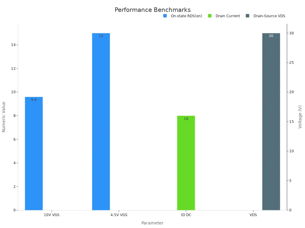
Modern electronics demand solutions that maximize efficiency and integration. The UPA2727UT1A-E1-AY addresses these needs with its compact 3.3 x 3.3 mm footprint, robust 16A current capability, and low 9.6 mΩ Rds(on). These features make it highly effective for power management and motor control in space-constrained environments.
Market growth for compact high-current MOSFETs remains strong, driven by electric vehicles and efficient power management needs:
|
Metric |
Value (2023) |
Forecast (2032) |
CAGR (2024-2032) |
|---|---|---|---|
|
Power MOSFET Modules Market |
USD 5.5 billion |
USD 9.3 billion |
6.2% |
Motor control applications benefit from the device’s efficient switching and thermal design:
Key Takeaways
-
The UPA2727UT1A-E1-AY MOSFET offers a small 3.3 x 3.3 mm package that saves board space while handling high currents up to 16A efficiently.
-
Low on-resistance and gate charge reduce power loss and support fast switching, improving overall system efficiency and battery life.
-
An exposed pad on the package enhances heat dissipation, ensuring stable operation even under heavy loads and in compact layouts.
-
This MOSFET suits power management and motor control applications, including DC/DC converters, battery protection, and automotive motor drives.
-
Following recommended PCB layout and thermal management practices maximizes device performance and reliability in demanding designs.
UPA2727UT1A-E1-AY Specifications
Electrical Specs
The UPA2727UT1A-E1-AY delivers strong electrical performance for demanding applications. Its specifications support efficient power management and reliable switching. The table below highlights the key electrical parameters:
|
Parameter |
Value |
|---|---|
|
Drain to Source Voltage (Vds) |
30 V |
|
Continuous Drain Current (Id) |
16 A @ 25°C |
|
On-Resistance (Rds(on)) |
9.6 mΩ @ Id=8 A, Vgs=10 V |
|
Gate Threshold Voltage (Vgs(th)) |
2.5 V @ 1 mA |
|
Total Gate Charge (Qg) |
11 nC @ Vgs=5 V |
|
Input Capacitance (Ciss) |
1170 pF @ Vds=15 V |
This device features a low on-resistance, which reduces conduction losses and improves overall efficiency. The low gate charge supports fast switching, making the UPA2727UT1A-E1-AY suitable for high-frequency circuits. The input capacitance remains moderate, which helps maintain quick response times in switching applications.
Package and Physical
The UPA2727UT1A-E1-AY uses an 8-DFN3333 package. This package measures only 3.3 mm by 3.3 mm, allowing engineers to save valuable board space. The surface-mount design enables easy integration into automated assembly lines. An exposed pad on the underside of the package enhances thermal management, helping the device maintain stable operation even under high current loads.
-
8-DFN3333 package (3.3 mm x 3.3 mm)
-
Surface-mount configuration
-
Exposed pad for improved heat dissipation
-
Bulk packaging for flexible inventory management
Note: The compact footprint and surface-mount design make this MOSFET ideal for space-constrained layouts and high-density assemblies.
The combination of small size, robust current handling, and effective thermal features ensures that the UPA2727UT1A-E1-AY meets the needs of modern power management and motor control systems.
Performance
Efficiency
Low on-resistance (Rds(on)) plays a key role in reducing power loss during operation. Engineers select devices with minimal Rds(on) to ensure less energy converts to heat. This feature leads to higher system efficiency, especially in power management and motor control circuits. The device’s total gate charge (Qg) remains low, which means the circuit requires less energy to switch the MOSFET on and off. Lower Qg also reduces switching losses, making the device suitable for high-frequency applications.
Tip: Choosing a MOSFET with low Rds(on) and Qg can help extend battery life in portable systems and reduce energy costs in industrial setups.
Thermal
Thermal management stands as a critical factor in high-current designs. The exposed pad on the underside of the 8-DFN3333 package allows direct heat transfer to the printed circuit board. This design helps maintain a lower junction temperature, even when the device operates at high currents. Effective heat dissipation ensures stable performance and prevents thermal runaway. Engineers can rely on this package to support compact layouts without sacrificing reliability.
-
Exposed pad improves heat flow to PCB
-
Compact package supports dense board designs
-
Stable operation under demanding loads
Switching
Fast switching performance depends on both low gate charge and low input capacitance. The device’s input capacitance (Ciss) remains moderate, which allows for rapid transitions between on and off states. This characteristic supports high-frequency switching in DC/DC converters and motor drives. Quick switching reduces energy loss during transitions and helps maintain precise control in dynamic circuits.
Note: Fast switching and low capacitance enable efficient operation in modern power electronics, where speed and accuracy matter.
UPA2727UT1A-E1-AY Applications
Power Management
Engineers often select the UPA2727UT1A-E1-AY for power management tasks that demand high efficiency and reliability. This MOSFET supports a range of applications, including:
-
DC/DC Converters: The device handles switching stages in buck and boost converter circuits, ensuring minimal power loss.
-
Battery Protection: It provides robust current handling for battery management systems, safeguarding cells from overcurrent events.
-
Uninterruptible Power Supplies (UPS): The MOSFET manages load switching and power distribution, maintaining system stability during outages.
-
Energy Storage: It enables efficient charge and discharge cycles in energy storage interfaces.
Note: The compact package and low Rds(on) make this device ideal for high-density power boards.
Motor Control
The UPA2727UT1A-E1-AY excels in motor control circuits, especially where space and efficiency matter. Designers use it in:
-
Small BLDC and DC Motor Drives: The device supports frequent switching and high current, which are essential for precise motor operation.
-
Automotive Systems: It appears in ADAS modules, electric and hybrid vehicle auxiliary circuits, and infotainment systems.
-
Industrial Automation: The MOSFET drives actuators and relays in factory equipment, supporting reliable and rapid response.
A table below summarizes typical motor control applications:
|
Application Area |
Example Use Case |
|---|---|
|
Automotive |
ADAS, EV/HEV power modules |
|
Industrial |
Conveyor and robotic drives |
|
Consumer Electronics |
Small appliance motors |
Other Uses
Beyond power and motor control, this MOSFET finds value in several sectors:
-
Telecom and Networking: It manages power paths in routers, switches, and cloud infrastructure.
-
Legacy Designs: Despite its obsolescence, the device remains a strong choice for existing products that require a compact, high-current N-channel MOSFET.
-
Space-Constrained Systems: The small footprint allows integration into dense layouts where board space is limited.
Engineers continue to rely on this device for both new and legacy projects that demand robust performance in tight spaces.
Design Tips
Layout
Engineers achieve optimal performance by focusing on PCB layout. Wide copper traces reduce resistance and support high current flow. Short, direct paths between the MOSFET and load minimize voltage drops and electromagnetic interference. Placing the device close to input and output capacitors helps maintain signal integrity and reduces switching noise.
Tip: Use multiple vias to connect the source pad to the ground plane. This approach lowers impedance and improves current handling.
A table below summarizes key layout practices:
|
Practice |
Benefit |
|---|---|
|
Wide traces |
Lower resistance |
|
Short connections |
Reduced voltage drop |
|
Multiple vias |
Enhanced current capacity |
|
Proximity to capacitors |
Improved noise suppression |
Engineers should avoid sharp corners in traces. Rounded or 45-degree angles help maintain consistent current flow and reduce hotspots.
Thermal Management
Effective thermal management ensures reliable operation under high loads. The exposed pad on the package provides a direct path for heat to move from the MOSFET to the PCB. Soldering the exposed pad to a large copper area on the board increases heat dissipation.
Note: Adding thermal vias beneath the exposed pad transfers heat to inner or bottom layers, spreading it across the board.
Designers often use thicker copper layers for power and ground planes. This choice further improves heat spreading. Placing the device away from other heat sources prevents localized overheating. If needed, engineers can add heatsinks or airflow to maintain safe operating temperatures.
By following these layout and thermal management tips, engineers can maximize device efficiency and reliability in compact, high-current designs.
Comparison
Alternatives
Engineers often evaluate several N-channel MOSFETs in the 30V, 10-20A class for power management and motor control. Popular alternatives include the IRLML6344, BSC016N02KS, and AO3400A. Each device offers a balance of current handling, on-resistance, and package size. The table below compares key parameters:
|
Device |
Vds (V) |
Id (A) |
Rds(on) (mΩ) |
Package |
Exposed Pad |
|---|---|---|---|---|---|
|
IRLML6344 |
30 |
5.7 |
22 |
SOT-23 |
No |
|
BSC016N02KS |
20 |
15 |
1.6 |
SuperSO8 |
Yes |
|
AO3400A |
30 |
5.8 |
13 |
SOT-23 |
No |
|
This Device |
30 |
16 |
9.6 |
8-DFN3333 |
Yes |
Note: Many alternatives offer lower current ratings or lack exposed pads for thermal management.
Unique Features
This device stands out in several ways:
-
Compact Size: The 3.3 mm x 3.3 mm 8-DFN3333 package saves board space in dense layouts.
-
Low On-Resistance: The 9.6 mΩ Rds(on) at 8A/10V reduces conduction losses, improving efficiency.
-
Robust Current Handling: The 16A continuous drain current supports demanding loads in power and motor control.
-
Exposed Pad: The package includes an exposed pad for direct heat transfer, enhancing thermal performance.
Engineers benefit from a combination of small footprint, high efficiency, and reliable thermal management. These features make this device a strong choice for compact, high-current designs.
The UPA2727UT1A-E1-AY offers engineers a compact solution with high current capability, low on-resistance, and strong thermal performance. This device supports efficient power management and precise motor control in space-limited designs.
-
Engineers can trust its reliability for demanding applications.
Consider the UPA2727UT1A-E1-AY for your next compact, high-current project to achieve both efficiency and robust performance.
FAQ
What makes the UPA2727UT1A-E1-AY suitable for compact designs?
The 8-DFN3333 package measures only 3.3 mm x 3.3 mm. This small footprint allows engineers to save board space in dense layouts. The exposed pad also helps with thermal management in tight spaces.
Can the UPA2727UT1A-E1-AY handle high switching frequencies?
Yes. The device features a low gate charge (Qg) of 11 nC and moderate input capacitance (Ciss) of 1170 pF. These parameters support fast switching and efficient operation in high-frequency circuits.
How does the exposed pad improve thermal performance?
The exposed pad provides a direct path for heat to move from the MOSFET to the PCB. This design lowers the junction temperature and supports stable operation under high current loads.
In which applications do engineers use this MOSFET most often?
|
Application Area |
Typical Use Case |
|---|---|
|
Power Management |
DC/DC converters, UPS |
|
Motor Control |
BLDC/DC drives, ADAS |
|
Industrial/Telecom |
Power switching, routers |
See Also
IRF820 N-Channel MOSFET For Power And Motor Control
Explore The LPQ252-CEF For Optimized Power Efficiency
Detailed Look At MC9S12DJ256MFUE For Automotive Use
Unveiling FREESCALE MCF5251CVM140’s Essential Auto Features
Harnessing AD74413RBCPZ To Enhance Process Control Systems