Networking equipment demands reliable and efficient USB connectivity to support modern applications. The USB2514BI-AEZG plays a pivotal role in meeting these requirements. Its ability to manage four USB 2.0 ports ensures seamless integration of multiple devices into a single hub. Features like full-speed and high-speed data transfer, overcurrent protection, and USB battery charging enhance its functionality. These capabilities make it indispensable in systems such as routers, switches, and IoT devices. By simplifying power distribution and improving data stability, the USB2514BI-AEZG ensures robust performance in diverse networking environments.
Key Takeaways
-
The USB2514BI-AEZG is a 4-port USB 2.0 hub. It helps connect devices and is useful for networking tools.
-
It can transfer data quickly, up to 480 Mbps. It also has safety features like overcurrent protection and battery charging.
-
To set it up, know the pin layout and give steady power. This stops problems with devices not being found.
-
Using tools like USB analyzers and oscilloscopes makes fixing issues easier. These tools help keep it working well.
-
Good PCB design and power planning make it more reliable. This helps it work better in different places.
Understanding the USB2514BI-AEZG
Overview of the USB2514BI-AEZG
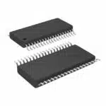
The USB2514BI-AEZG is a versatile 4-port USB 2.0 hub controller designed to enhance connectivity in various applications. It supports high-speed (480 Mbps) and full-speed (12 Mbps) data transfer rates, making it suitable for both consumer and industrial environments. This component simplifies the integration of multiple USB devices into a single system, ensuring efficient communication and power management. Its compact design and low power consumption make it ideal for space-constrained and energy-sensitive applications.
The USB2514BI-AEZG finds use in a wide range of scenarios. In consumer electronics, it enables seamless connectivity for devices like smart TVs and gaming consoles. In industrial automation, it ensures reliable communication between sensors and controllers. Automotive applications benefit from its ability to connect infotainment systems and GPS units. Additionally, it supports healthcare devices by facilitating data transfer in diagnostic and monitoring systems. These diverse use cases highlight its adaptability and importance in modern technology.
Key Features and Specifications
The USB2514BI-AEZG offers a robust set of features that make it stand out in the market. Below is a table summarizing its critical features:
|
Feature |
Description |
|---|---|
|
4 USB 2.0 Ports |
Supports four downstream USB 2.0 ports for multiple device connections. |
|
Full-Speed and High-Speed Rates |
Compatible with full-speed (12 Mbps) and high-speed (480 Mbps) data transfer rates. |
|
USB Battery Charging |
Supports USB battery charging for devices needing power through USB. |
|
Overcurrent Protection |
Built-in protection against electrical faults for safety. |
|
Low Power Consumption |
Designed for energy efficiency, reducing power usage when devices are idle. |
In addition to these features, the USB2514BI-AEZG adheres to USB-IF standards and RoHS directives, ensuring compliance with industry regulations. It also includes an integrated DC-DC converter, which simplifies power management during integration. These specifications make it a reliable choice for applications requiring efficient USB connectivity.
Hardware Integration
Pinout and Connection Guide
Integrating the USB2514BI-AEZG into a system begins with understanding its pinout configuration. This 4-port USB 2.0 hub controller features dedicated pins for power, ground, data lines, and control signals. Proper connections ensure stable operation and reliable data transfer.
-
Key Pin Connections:
-
Vdd Pin: Supplies the 3.3V power required for the hub’s operation.
-
D+ and D- Pins: Handle USB data transmission for each downstream port.
-
Ground Pins: Provide a common reference point for the circuit.
-
Reset Pin: Resets the hub controller during initialization.
-
When connecting the USB2514BI-AEZG, ensure that all pins are securely soldered to avoid loose connections. Use high-quality connectors to maintain signal integrity and reduce the risk of device detection failures.
Power Supply Requirements
The USB2514BI-AEZG requires a stable 3.3V power supply for optimal performance. Voltage fluctuations can lead to malfunctioning or device detection issues. To prevent this, ensure the Vdd pin receives clean and consistent power. For systems with high-power peripherals, confirm that the power source provides sufficient current to support all connected devices.
In some cases, the hub may also require a stable 5V supply for downstream devices. Each USB port should deliver up to 500mA to meet USB 2.0 specifications. Proper power distribution is critical for avoiding slow data transfer rates or device disconnections.
PCB Layout Tips
Designing an efficient PCB layout for the USB2514BI-AEZG involves several best practices. These guidelines help maintain signal integrity and minimize noise:
-
Use controlled impedance traces for the USB data lines (D+ and D-). This ensures consistent signal quality.
-
Match the lengths of the D+ and D- traces to avoid timing mismatches.
-
Terminate the data lines properly to reduce signal reflections.
-
Implement a solid, uninterrupted ground plane to improve power distribution and reduce noise.
-
Minimize trace lengths to lower parasitic inductance and capacitance.
By following these tips, designers can create a robust PCB layout that supports the USB2514BI-AEZG’s functionality while reducing the likelihood of hardware issues.
Software Configuration
Configuring the USB2514BI-AEZG
Configuring the USB2514BI-AEZG involves setting up its firmware and ensuring compatibility with the host system. The process begins by connecting the hub controller to the host device and verifying its detection. Developers should use debugging tools to monitor the USB device enumeration process. Proper configuration ensures that all four USB ports function as intended, supporting high-speed data transfer and power management.
Firmware customization may be necessary for specific applications. Developers should review the firmware logs to identify potential issues. Implementing error-handling mechanisms can prevent device enumeration failures. Reflashing the firmware can resolve persistent problems. Ensuring the host controller drivers are up-to-date is also critical for smooth operation.
Tools and Utilities
Several tools and utilities simplify the configuration and troubleshooting of the USB2514BI-AEZG:
-
USB Protocol Analyzers: Monitor data traffic between the USB host and connected devices. These tools help identify issues like data corruption or communication failures.
-
Oscilloscopes: Analyze electrical signals to detect power-related problems such as voltage drops or noise.
-
Power Measurement Tools: Measure current and voltage to ensure proper power distribution across all USB ports.
-
Debugging Software: Applications like USBView provide real-time information about connected USB devices, aiding in software-related diagnostics.
Selecting the right tools ensures efficient configuration and reduces the time spent resolving issues.
Common Configuration Settings
During software setup, developers often encounter challenges that require attention to detail. Common issues include:
-
PCB Layout Optimization: Poor design can lead to data transfer errors. Using controlled impedance traces and maintaining a solid ground plane can mitigate these problems.
-
Handling USB Host Controller Issues: Outdated drivers or communication breakdowns can disrupt the system. Monitoring USB traffic with a protocol analyzer helps identify these issues.
-
Firmware Debugging: Bugs in the firmware can cause device detection failures. Reviewing logs and implementing robust error-handling mechanisms can address these challenges.
-
Environmental Factors: Electromagnetic interference (EMI) or high temperatures can affect performance. Shielding the hub and monitoring operating conditions can prevent such issues.
By addressing these settings, developers can ensure the USB2514BI-AEZG operates reliably in various environments.
Testing and Validation
Verifying Hardware Connections
Proper hardware validation ensures the USB2514BI-AEZG operates reliably in networking systems. Following a systematic approach helps identify and resolve potential issues efficiently:
-
Monitor USB Traffic and Data Flow: Use a USB protocol analyzer to capture data flow. Look for error codes that indicate data corruption or communication failures.
-
Evaluate Hub Port Overload and Bandwidth Allocation: Confirm that connected devices share bandwidth evenly to prevent performance bottlenecks.
-
Investigate Power Management and Overcurrent Issues: Check the hub’s overcurrent status. For high-power devices, consider using an external power source.
-
Test the USB2514BI-AEZG in Isolation: Disconnect unnecessary peripherals and test the hub in a different system to rule out external factors.
Tip: Tools like oscilloscopes and power measurement devices can provide deeper insights into electrical signals and power distribution.
Debugging Common Issues
Debugging ensures smooth operation by addressing common challenges. Optimizing the PCB layout is crucial for maintaining signal integrity and power distribution. Controlled impedance traces, a solid ground plane, and minimized trace lengths reduce data transfer errors.
Effective debugging techniques include:
-
Signal Integrity Checks: Use oscilloscopes to detect signal quality issues.
-
Power Supply Monitoring: Measure voltage fluctuations to ensure stable power delivery.
-
Firmware Debugging: Update firmware to resolve communication errors.
-
Loopback Tests: Connect the USB host directly to the hub to isolate functionality.
-
Environmental Testing: Assess performance under varying conditions like temperature and electromagnetic interference.
Note: Debugging software provides real-time information about USB devices, making it easier to identify software-related issues.
Performance Testing
Performance testing evaluates the USB2514BI-AEZG’s reliability under different scenarios. Key methods include:
-
Using a USB analyzer to monitor data flow and detect bottlenecks.
-
Performing signal integrity checks with oscilloscopes to ensure data quality.
-
Conducting loopback tests to verify the hub’s functionality.
-
Testing under various environmental conditions to confirm robustness.
-
Monitoring power supply to prevent device recognition issues.
Reminder: Testing the hub in isolation can help eliminate external factors that may affect performance.
These steps ensure the USB2514BI-AEZG delivers optimal performance in networking applications.
Best Practices for USB2514BI-AEZG Integration
Integrating the USB2514BI-AEZG involves several critical steps to ensure optimal performance. Key actions include verifying hardware connections, configuring software settings, and conducting thorough testing. Following best practices, such as optimizing PCB layouts and shielding against electromagnetic interference, enhances reliability. Debugging tools like USB protocol analyzers and oscilloscopes simplify troubleshooting, while firmware updates address potential issues.
The outlined process applies to various fields, including consumer electronics, industrial automation, and healthcare. By adhering to these guidelines, developers can achieve seamless implementation and unlock the full potential of the USB2514BI-AEZG in their systems.
What is the primary function of the USB2514BI-AEZG?
The USB2514BI-AEZG serves as a 4-port USB 2.0 hub controller. It enables multiple USB devices to connect to a single host system. It supports high-speed data transfer and efficient power management, making it ideal for networking, consumer electronics, and industrial applications.
How does the USB2514BI-AEZG handle power distribution?
The USB2514BI-AEZG includes an integrated DC-DC converter. It ensures stable power delivery to all connected devices. Each USB port can provide up to 500mA, adhering to USB 2.0 specifications. Overcurrent protection safeguards the system from electrical faults.
Can the USB2514BI-AEZG support USB battery charging?
Yes, the USB2514BI-AEZG supports USB battery charging. It allows connected devices to draw power through the USB ports. This feature is particularly useful in applications like USB charging stations and docking systems.
What tools are recommended for debugging the USB2514BI-AEZG?
USB protocol analyzers, oscilloscopes, and power measurement tools are essential for debugging. These tools help monitor data traffic, analyze signal integrity, and ensure proper power distribution. Debugging software like USBView provides real-time device information for troubleshooting.
What are the key PCB layout tips for integrating the USB2514BI-AEZG?
Designers should use controlled impedance traces for USB data lines. Matching trace lengths for D+ and D- ensures timing accuracy. A solid ground plane reduces noise, while proper termination minimizes signal reflections. Shorter trace lengths improve overall performance and reliability.
See Also
Simplified Networking Strategies For XILINX XC7K325T
Streamlined Sensor Integration Techniques For SN74LVC4245APW
Choosing The Right Controller: CYUSB3014-BZXI Or BZXC?
Harnessing ARTESYN NPT42-M For Industrial Automation Solutions
Three Effective Methods For Integrating MC9S12XET512VAG