Zener diodes and BJTs, such as the PNP transistor BC327, play a crucial role in protecting power systems by preventing component failure during voltage and current surges. Zener diodes and BJTs supply reliable voltage regulation, with Zener diodes managing avalanche breakdown in a controlled manner to avoid overheating and damage. Meanwhile, BJTs, including the PNP transistor BC327, effectively handle current to safeguard against overcurrent and short circuits. Together, they ensure thermal stability, preventing localized overheating that could damage silicon crystals. These components also provide inrush current protection, enabling smooth power delivery, and work seamlessly with current limiting ICs to enhance overall system safety.
Key Takeaways
-
Zener diodes keep voltage steady by letting current flow at a set voltage. This stops circuits from getting too much voltage.
-
BJTs, like the PNP transistor BC327, make current stronger and work as switches. They stop too much current and short circuits in power systems.
-
Using Zener diodes and BJTs together makes circuits safer. They keep voltage and current at safe levels for smooth operation.
-
Picking the right Zener diode and BJT is important. It helps control voltage and current, keeping circuits stable for a long time.
-
Good heat control in circuit design stops overheating. This makes power systems work better and last longer.
Understanding Zener Diodes
Zener diodes are essential components in modern electronics, particularly for managing voltage faults and ensuring stable power delivery. Their ability to regulate voltage and protect circuits from overvoltage conditions makes them indispensable in circuit protection devices. This section explores how Zener diodes work, their role as voltage regulators, and their applications in safeguarding electronic systems.
How Zener Diodes Work
Zener diodes operate based on a unique principle called reverse breakdown. Unlike standard diodes, which block current in reverse bias, Zener diodes allow current to flow once the reverse voltage exceeds a specific threshold, known as the breakdown voltage. This behavior enables them to maintain a nearly constant voltage across their terminals, even when the input voltage fluctuates.
Key principles of Zener diode operation include:
-
Reverse Bias Operation: Zener diodes function in reverse bias, stabilizing voltage by conducting excess current.
-
Voltage Stabilization: In the breakdown region, the voltage remains steady, regardless of current variations.
-
Dynamic Resistance: The steep slope of the V-I curve in the breakdown region ensures effective voltage regulation.
The ability to maintain a stable voltage under varying conditions makes Zener diodes ideal for addressing system power faults caused by voltage fluctuations.
Zener Diodes as Voltage Regulators
The role of a Zener diode as a voltage regulator is crucial in electronic circuits. By acting as a shunt regulator, it diverts excess current to maintain a constant output voltage. This capability ensures that sensitive components remain protected from overvoltage conditions.
The following steps illustrate how Zener diodes regulate voltage:
-
The Zener diode conducts current when the input voltage exceeds its breakdown voltage.
-
A current-limiting resistor in series with the diode prevents excessive current flow, ensuring safe operation.
-
The voltage across the load connected in parallel with the Zener diode remains stable, even if the supply voltage or load current changes.
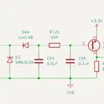
For example, in a power supply circuit, a Zener diode can maintain a stable output voltage of 5.1V, protecting devices from voltage faults. This stability is vital for applications requiring precise voltage levels, such as microcontroller-based systems.
|
Performance Metric |
Description |
|---|---|
|
Maximum Reverse Current |
The highest current a Zener diode can handle in reverse bias, crucial for transient conditions. |
|
Power Rating |
Indicates the maximum power the diode can continuously handle, affecting its reliability. |
|
Voltage Tolerance |
Shows the acceptable variation in breakdown voltage, ensuring stable operation. |
|
Temperature Stability |
Describes how breakdown voltage varies with temperature, important for consistent performance. |
|
Zener Resistance |
The dynamic resistance during breakdown, impacting output voltage stability in regulation. |
These performance metrics highlight the reliability of Zener diodes in voltage regulation, even under challenging conditions like temperature faults or load variations.
Applications of Zener Diodes in Circuit Protection Devices
Zener diodes play a pivotal role in circuit protection devices by safeguarding electronic systems from overvoltage and other power-related issues. Their fast response time and precise voltage regulation make them suitable for a wide range of applications.
Some common applications include:
-
Power Supply Protection: Zener diodes prevent overvoltage conditions in power supplies, ensuring stable operation.
-
Signal Line Protection: They protect sensitive signal lines from voltage spikes, enhancing system reliability.
-
Voltage Reference: Zener diodes provide a stable reference voltage for analog and digital circuits.
-
Transient Voltage Suppression: Their ability to clamp voltage spikes makes them effective in protecting against system power faults.
A study on Zener diodes under DC switching surge conditions revealed their robustness in circuit protection. The maximum average surge currents recorded before failure ranged from 1.98 A to 3.33 A, depending on the manufacturer. This data underscores their effectiveness in handling transient conditions and maintaining system stability.
|
Parameter |
Value Range |
|---|---|
|
Forward Clamping Voltage |
0.7 V – 0.8 V |
|
Reverse Clamping Voltage |
27 V – 30 V |
|
Nominal Limiting Voltage |
25 V |
|
Measured Pulse Clamping Voltage |
~20% higher than nominal |
|
Response Time |
< 1 ns |
These characteristics demonstrate the versatility of Zener diodes in protecting circuits from voltage faults and ensuring reliable performance in various applications.
Role of BJTs in Power Protection
Bipolar Junction Transistors (BJTs) are indispensable components in power systems, offering robust solutions for managing current faults and ensuring reverse voltage protection. Their ability to amplify current and switch signals efficiently makes them a cornerstone of modern circuit protection designs.
Current Amplification and Switching Capabilities
BJTs excel in current amplification, a critical function in power systems. By controlling a small base current, they enable the flow of a much larger current between the collector and emitter terminals. This property allows BJTs to drive high-power loads while maintaining precise control over the circuit.
In addition to amplification, BJTs serve as reliable switches. When used in saturation mode, they act as closed switches, allowing current to flow freely. In cutoff mode, they function as open switches, blocking current flow. These switching capabilities are essential for applications requiring rapid transitions between on and off states, such as motor control and power regulation.
Tip: BJTs are particularly effective in circuits where both amplification and switching are required, making them versatile components for power protection.
Applications across industries highlight the importance of BJTs in power systems:
-
Consumer Electronics: BJTs amplify and switch signals in devices like televisions and personal computers, ensuring energy efficiency.
-
Automotive Industry: They manage power in electric and hybrid vehicles, enhancing the reliability of ignition systems and electronic control units.
-
Industrial Sector: BJTs regulate power in automated systems, improving energy efficiency and operational stability.
-
Telecommunications: They amplify signals in base stations and routers, maintaining signal integrity for high-speed internet.
Preventing Overcurrent and Short Circuit Protection with BJTs
BJTs play a vital role in preventing overcurrent and providing short circuit protection. Overcurrent conditions, often caused by sudden surges or faulty components, can damage sensitive electronics. BJTs mitigate these risks by limiting the current flow through their base-emitter junction.
In short circuit protection, BJTs act as current-limiting devices. When a short circuit occurs, the transistor reduces the current to a safe level, preventing damage to the circuit. This functionality is particularly useful in power supplies and motor control systems, where current faults can lead to catastrophic failures.
For reverse voltage protection, BJTs can be configured to block unwanted reverse currents. This setup ensures that power flows in the intended direction, safeguarding components from damage caused by reverse polarity connections.
Practical Examples Using the PNP Transistor BC327
The PNP transistor BC327 is a popular choice for low-power applications requiring precise current control. Its ability to handle moderate currents and voltages makes it suitable for a variety of circuit designs.
One practical example involves using the BC327 in a 3-phase driver circuit. This setup controls a low-power 3-phase load with an ATTiny85 microcontroller. The circuit incorporates fast 1N4148 diodes and resistors to manage switching and protect against inductive spikes. The BC327 ensures smooth operation by providing reliable current amplification and reverse voltage protection.
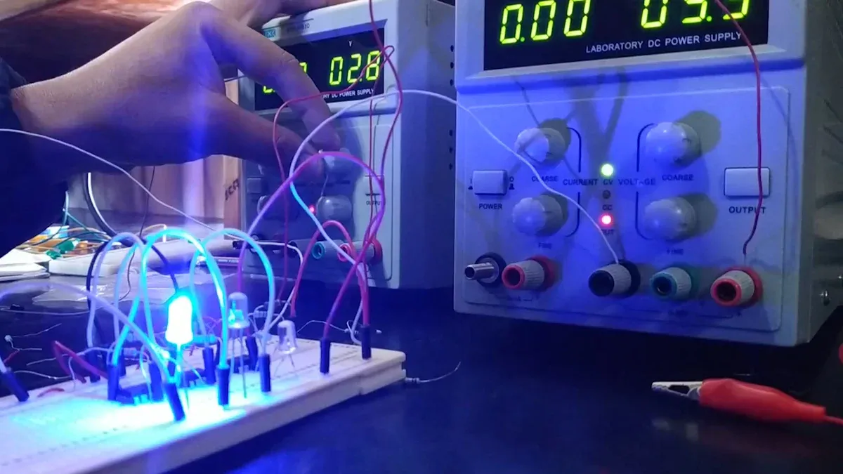
Another application of the BC327 is in LED driver circuits. By regulating the current through the LEDs, the transistor prevents overcurrent conditions, extending the lifespan of the LEDs. This demonstrates the versatility of the BC327 in both power protection and energy-efficient designs.
Note: The BC327’s compact size and reliable performance make it an excellent choice for applications where space and efficiency are critical.
BJTs, including the PNP transistor BC327, continue to prove their value in safeguarding power systems. Their ability to amplify current, switch signals, and provide short circuit protection ensures the reliability and safety of modern electronic devices.
Combining Zener Diodes and BJTs for Enhanced Protection
How Zener Diodes and BJTs Work Together
Zener diodes and BJTs form a powerful combination in circuit protection methods. Zener diodes regulate voltage by clamping excess voltage, while BJTs manage current flow and prevent overcurrent. Together, they create a dual-layer defense that protects sensitive components from electrical faults.
For instance, a Zener diode can stabilize voltage across a load, while a BJT amplifies or limits current based on the circuit’s needs. This synergy ensures both voltage and current remain within safe operating limits. Additionally, BJTs enhance thermal protection by dissipating heat generated during high-current conditions. This prevents localized overheating, which could damage the circuit.
Circuit Examples Featuring Zener Diodes and BJTs
A common example of their combined use is in overvoltage protection circuits. In such designs, a Zener diode clamps the voltage to a safe level, while a BJT acts as a switch to disconnect the load if the current exceeds a preset threshold.
Another example involves motor control circuits. Here, the Zener diode stabilizes the supply voltage, and the BJT regulates the motor’s current. This setup ensures smooth operation and protects the motor from thermal damage caused by excessive current.
Tip: Adding a heat sink to the BJT can further improve thermal protection in high-power applications.
Advantages of Combining These Components in Power Systems
The integration of Zener diodes and BJTs offers several benefits:
-
Enhanced Reliability: Their combined action ensures robust protection against voltage and current faults.
-
Improved Thermal Protection: BJTs dissipate heat effectively, reducing the risk of overheating.
-
Versatility: This pairing suits a wide range of applications, from power supplies to motor controllers.
-
Cost-Effectiveness: Using these components together reduces the need for complex protection circuits.
This combination provides a comprehensive solution for safeguarding power systems, ensuring long-term performance and reliability.
Design Tips and Best Practices
Selecting the Right Zener Diode for Voltage Regulation
Choosing the correct Zener diode ensures effective voltage regulation and circuit protection. Several factors must be evaluated to match the diode to the application’s requirements:
-
Voltage Rating: The breakdown voltage should exceed the maximum operating voltage of the circuit.
-
Power Dissipation: The diode must handle heat effectively without exceeding its power limits.
-
Package Type: Compatibility with the circuit board layout and assembly constraints is essential.
When selecting a Zener diode, specific performance metrics also play a critical role:
-
Zener Voltage: The reverse voltage at which the diode begins conducting.
-
Maximum and Minimum Zener Current: These define the current range for stable operation.
-
Power Dissipation: The maximum power the diode can safely dissipate.
-
Temperature Stability: Ensures consistent performance across varying temperatures.
-
Voltage Tolerance: Indicates the precision of the breakdown voltage.
-
Zener Impedance: Affects voltage stability under current variations.
-
Leakage Current: The small current flowing below the breakdown threshold.
-
Junction Temperature: The maximum temperature the diode can withstand.
Selecting a diode with the right combination of these parameters ensures reliable voltage regulation and long-term circuit stability.
Choosing the Appropriate BJT for Current Control
Selecting the right BJT involves understanding the current and voltage requirements of the circuit. The transistor must handle the maximum load current without overheating or failing. Key considerations include:
-
Current Gain (hFE): Determines how much the base current amplifies to drive the load.
-
Collector-Emitter Voltage (Vce): Should exceed the circuit’s operating voltage.
-
Power Dissipation: The transistor must dissipate heat effectively during operation.
For example, the PNP transistor BC327 is ideal for low-power applications. It offers moderate current handling and voltage ratings, making it suitable for circuits like LED drivers and motor controllers. Its compact package also supports space-constrained designs.
Tip: Always verify the transistor’s thermal limits and use heat sinks or cooling mechanisms for high-power applications.
Optimizing Circuit Layout for Thermal Management
Effective thermal management prevents overheating and ensures circuit reliability. Proper layout design minimizes thermal stress and enhances heat dissipation. Techniques include:
-
Component Placement: Position heat-generating components away from sensitive parts.
-
Thermal Vias: Use vias to transfer heat to the PCB’s ground plane or heat sink.
-
Copper Traces: Wider traces improve heat conduction and reduce resistance.
Advanced tools like the Cadence Celsius Thermal Solver assist in optimizing thermal performance. This software integrates electro-thermal simulations, enabling designers to detect hot spots early in the design phase. It reduces development iterations and ensures efficient heat dissipation.
Packaging innovations, such as TI’s HotRod QFN, further enhance thermal performance. By eliminating wire-bonding, these packages improve heat dissipation and lower operational temperatures, making them ideal for high-power applications.
Note: Early thermal analysis during the design phase prevents costly revisions and ensures reliable circuit operation.
Testing and Validating Protective Circuit Designs
Testing and validating protective circuit designs ensure their reliability and effectiveness in real-world applications. Engineers must follow a systematic approach to identify potential issues and confirm that the circuit meets performance requirements.
Key Steps in Testing Protective Circuits
-
Visual Inspection
Engineers begin by examining the circuit layout for errors such as incorrect connections or soldering defects. This step helps identify physical issues before powering the circuit. -
Component Verification
Each component, including Zener diodes and BJTs, must be tested individually. A multimeter can measure the Zener diode’s breakdown voltage and verify the BJT’s base-emitter junction functionality. -
Functional Testing
The circuit is powered under controlled conditions to observe its behavior. Engineers apply input voltages and currents within and beyond the expected range to test the circuit’s response. -
Stress Testing
The circuit undergoes stress tests to simulate extreme conditions, such as voltage spikes or overcurrent scenarios. This step ensures the protective components activate as intended. -
Thermal Analysis
Engineers monitor the circuit’s temperature during operation. Infrared cameras or thermal probes help detect overheating, which could indicate design flaws.
Tools for Circuit Validation
|
Tool |
Purpose |
|---|---|
|
Multimeter |
Measures voltage, current, and resistance |
|
Oscilloscope |
Observes voltage waveforms and spikes |
|
Thermal Camera |
Detects heat distribution in components |
|
Function Generator |
Simulates input signals for testing |
Tip: Always document test results to track performance and identify trends during iterative design improvements.
Importance of Validation
Validation ensures the circuit operates as expected under all conditions. It confirms that Zener diodes regulate voltage effectively and BJTs manage current without failure. Proper testing reduces the risk of component damage and enhances the overall reliability of power systems.
Zener diodes and BJTs, such as the PNP transistor BC327, play a critical role in protecting power systems. Their combined functionality ensures stable voltage regulation, precise current control, and effective short circuit protection. Together, they create a reliable defense against electrical faults.
Key Takeaway: Engineers can design efficient power systems by integrating these components and following best practices. This approach minimizes component damage and enhances long-term performance, ensuring safety and reliability in modern electronics.
By leveraging these technologies, power systems achieve greater stability and resilience in demanding applications.
What is the primary role of a fuse in power systems?
A fuse protects circuits by breaking the connection when excessive current flows. It prevents damage to components by interrupting the circuit during overcurrent conditions. This simple yet effective device ensures safety and reliability in power systems.
How do Zener diodes and BJTs differ from a fuse?
Zener diodes and BJTs regulate voltage and current, while a fuse provides overcurrent protection by physically disconnecting the circuit. Unlike a fuse, Zener diodes and BJTs can repeatedly operate without replacement, making them ideal for dynamic circuit protection.
Can a fuse be used alongside Zener diodes and BJTs?
Yes, a fuse complements Zener diodes and BJTs by adding an extra layer of protection. While Zener diodes and BJTs handle voltage and current regulation, the fuse safeguards against extreme overcurrent scenarios, ensuring comprehensive circuit protection.
Why is a fuse necessary in high-power applications?
High-power systems often experience sudden current surges. A fuse prevents catastrophic failures by disconnecting the circuit during such events. Its fast response time makes it essential for protecting expensive components in industrial and commercial setups.
How does a fuse enhance the reliability of power systems?
A fuse ensures that power systems remain operational by preventing damage from overcurrent faults. Its ability to isolate faulty sections of a circuit minimizes downtime and reduces the risk of widespread failures, enhancing overall system reliability.
See Also
Harnessing The Power Of ARTESYN NPT42-M For Automation
Explore The LPQ252-CEF For Optimal Power Efficiency
IRF820: A Versatile N-Channel MOSFET For Power Control
Comprehensive Guide To Using AD620AN In Television Power
Enhancing Process Control With The AD74413RBCPZ Solution