Precision and reliability form the backbone of modern data acquisition systems. Recent advancements in sensor technology have enabled these systems to capture data with exceptional accuracy, which is vital for industries like manufacturing and scientific research. The MAX9032AUA+T offers a robust solution for voltage comparison and signal conditioning. Its features, such as dual independent comparators and low power consumption, make it ideal for applications requiring precise measurements. By integrating this versatile component, engineers can enhance system performance while maintaining efficiency and reliability.
Key Takeaways
-
The MAX9032AUA+T is a chip that compares voltages accurately. This makes it important for collecting correct data in many devices.
-
It uses very little power, only 35µA, which helps batteries last longer. This makes it great for portable gadgets and energy-saving systems.
-
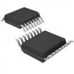
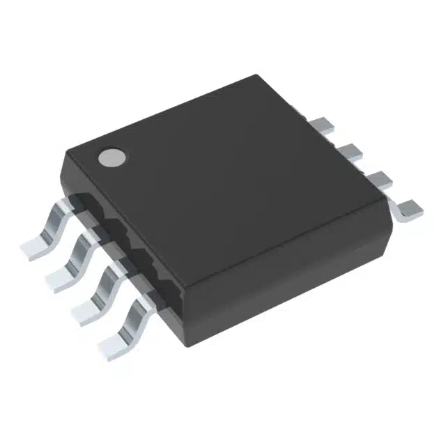
Its small MSOP-8 size fits easily into tight spaces. This helps save space on circuit boards without losing performance.
-
Engineers should use steady power and good signal setups to get the best results from the MAX9032AUA+T.
-
Using guides like datasheets and notes from the maker can make setup easier and solve common problems.
Understanding the MAX9032AUA+T
What is the MAX9032AUA+T?
The MAX9032AUA+T is a dual comparator integrated circuit designed for precise voltage comparison tasks. It features two independent comparators within a compact MSOP-8 package, making it suitable for space-constrained systems. The device operates with an input offset voltage of just 1mV and an input bias current of 8nA, ensuring high accuracy in voltage detection. Its wide operating temperature range allows it to perform reliably in diverse environments, from industrial settings to portable devices. These specifications distinguish the MAX9032AUA+T from similar components, making it a preferred choice for engineers.
|
Specification |
Detail |
|---|---|
|
Package |
MSOP-8 |
|
Input Offset Voltage |
1mV |
|
Input Bias Current |
8nA |
|
Operating Temperature Range |
Wide range suitable for various applications |
Why is the MAX9032AUA+T essential for data acquisition systems?
Data acquisition systems rely on accurate voltage comparisons to process and analyze signals effectively. The MAX9032AUA+T enhances these systems by providing high-speed and precise voltage detection. Its low power consumption makes it ideal for battery-operated devices, ensuring efficiency without compromising performance. The compact design of the MAX9032AUA+T allows seamless integration into modern systems, even those with limited space. By incorporating this component, engineers can achieve greater reliability and precision in their data acquisition processes.
Applications of the MAX9032AUA+T in data acquisition
The MAX9032AUA+T serves various roles in data acquisition systems. It can function as a voltage level detector, monitoring specific thresholds to trigger events or protect sensitive components. In analog-to-digital conversion systems, it compares input signals against reference values before passing data to microcontrollers or ADCs. The device also supports window comparator configurations, ensuring signals remain within predefined voltage ranges. These capabilities make the MAX9032AUA+T indispensable in applications such as battery monitoring, fault detection, and signal conditioning.
Key Features and Benefits of the MAX9032AUA+T
High-speed and precise voltage comparison
The MAX9032AUA+T delivers exceptional performance in high-speed and precise voltage comparison tasks. Its low input offset voltage of 1mV and input bias current of 0.008µA ensure accurate voltage detection, even in sensitive applications. The device achieves a maximum propagation delay of 228ns, enabling rapid response times in critical systems. Engineers can rely on its high common-mode rejection ratio (CMRR) and power supply rejection ratio (PSRR), both rated at 100dB, to maintain accuracy under varying conditions. These attributes make the MAX9032AUA+T a reliable choice for applications requiring fast and precise signal processing.
|
Parameter |
Value |
|---|---|
|
Input Offset Voltage |
1mV Max at 5V |
|
Input Bias Current |
0.008µA Max at 5V |
|
Propagation Delay |
228ns Max |
|
CMRR |
100dB Typical |
|
PSRR |
100dB Typical |
Low power consumption for portable devices
The MAX9032AUA+T excels in portable applications due to its low power consumption. With a supply current of just 35µA, it supports efficient operation in battery-powered devices. Its single-supply operation, which functions down to +2.5V, enhances portability by reducing power requirements. These features extend battery life, making the MAX9032AUA+T ideal for portable data acquisition systems. Engineers can integrate this component into devices like handheld monitors and battery-operated sensors without compromising performance.
|
Feature |
Benefit |
|---|---|
|
Low Power Consumption |
Extends battery life in portable devices |
|
Power Efficiency |
Ideal for battery-powered applications |
|
Low 35µA Supply Current |
Supports efficient operation in portable apps |
|
Single-supply operation |
Operates down to +2.5V, enhancing portability |
Compact design for space-constrained systems
The compact design of the MAX9032AUA+T ensures seamless integration into space-constrained systems. Its surface-mountable package options, including 8-MSOP and 6-WLP, allow engineers to optimize board layouts. The device’s small footprint, combined with a quiescent current of 55µA, makes it suitable for applications where space and power efficiency are critical. Its wide operating temperature range of -40°C to 125°C ensures reliable performance in diverse environments, from industrial machinery to portable electronics.
|
Feature |
Specification |
|---|---|
|
Mounting Type |
Surface Mount |
|
Supplier Device Package |
8-SOIC, 8-uMAX/uSOP, 6-WLP, SOT-23-5 |
|
Package / Case |
8-SOIC (0.154′, 3.90mm Width), 8-TSSOP, 8-MSOP (0.118′, 3.00mm Width), 6-WFBGA, WLBGA, SC-74A, SOT-753 |
|
Current – Quiescent (Max) |
55µA |
|
Voltage – Supply |
2.5V ~ 5.5V |
|
Operating Temperature |
-40°C ~ 125°C |
Flexibility in power supply and integration
The MAX9032AUA+T offers exceptional flexibility in power supply and integration, making it a valuable component for modern data acquisition systems. Its wide supply voltage range, from 2.5V to 5.5V, allows it to operate seamlessly in various environments. This adaptability ensures compatibility with both low-voltage and standard-voltage systems, providing engineers with greater design freedom. The device’s rail-to-rail output further enhances its versatility, enabling precise signal processing across the entire voltage range.
Low power consumption is another key advantage of the MAX9032AUA+T. With a supply current of just 35µA, it supports energy-efficient operation, especially in battery-powered devices. This feature makes it ideal for portable applications, where conserving power is critical. The device also integrates easily into high-speed systems due to its fast response time, ensuring reliable performance in time-sensitive applications.
The MAX9032AUA+T’s design simplifies integration into existing systems. Its compact package options, such as MSOP-8 and WLP, reduce the space required on circuit boards. This compactness is particularly beneficial for space-constrained applications, such as handheld devices or embedded systems. Additionally, the device’s high precision and low input offset voltage ensure accurate operation, even in complex configurations.
The table below highlights the features that contribute to the MAX9032AUA+T’s flexibility in power supply and integration:
|
Feature |
Description |
|---|---|
|
Supply Voltage Range |
2.5V to 5.5V |
|
Low Power Consumption |
Yes |
|
High Precision Operation |
Yes |
|
Rail-to-Rail Output |
Yes |
|
Fast Response Time |
Suitable for High-Speed Signaling |
By combining these features, the MAX9032AUA+T provides a reliable and adaptable solution for engineers. Its flexibility ensures seamless integration into diverse systems, enhancing both performance and efficiency.
Step-by-Step Guide to Integrating the MAX9032AUA+T
Hardware considerations
Power supply requirements and configurations
Proper power supply configuration ensures the MAX9032AUA+T operates efficiently. The device supports a supply voltage range of 2.5V to 5.5V, making it compatible with both low-voltage and standard-voltage systems. Engineers should select a stable power source to minimize noise and fluctuations. Decoupling capacitors, such as a 0.1µF ceramic capacitor placed close to the IC, help reduce power supply noise. For systems with multiple voltage levels, designers should ensure the supply voltage matches the operating range of the MAX9032AUA+T to avoid performance issues.
Signal conditioning and input setup
Accurate signal conditioning is critical for optimal performance. The MAX9032AUA+T requires proper input signal levels to ensure precise voltage comparison. Engineers should use resistive dividers or operational amplifiers to scale input signals within the device’s input voltage range. Additionally, filtering capacitors can be added to suppress high-frequency noise. For differential inputs, designers should ensure balanced signal paths to maintain signal integrity. Proper grounding techniques, such as connecting the ground pin to a low-impedance ground plane, further enhance performance.
Software considerations
Setting thresholds and hysteresis
Configuring thresholds and hysteresis ensures reliable operation in noisy environments. Engineers can set voltage thresholds using external resistors connected to the reference input. Hysteresis, achieved by adding a feedback resistor, prevents rapid switching caused by small signal variations. This setup stabilizes the comparator’s output and improves system reliability.
Synchronizing with other system components
Synchronization with other components ensures seamless integration. Engineers should align the comparator’s output timing with the system’s clock or control signals. This can be achieved by adjusting the propagation delay or using external timing circuits. Proper synchronization prevents timing conflicts and enhances overall system performance.
Communication interfaces
Interfacing with microcontrollers or processors
The MAX9032AUA+T integrates easily with microcontrollers or processors. Its digital output can connect directly to GPIO pins, enabling real-time signal monitoring. Engineers should configure the microcontroller to interpret the comparator’s output as a logic high or low signal. Pull-up or pull-down resistors may be required to stabilize the output in certain configurations.
Ensuring compatibility with existing systems
Compatibility with existing systems is essential for smooth integration. Engineers should verify that the comparator’s output voltage levels match the input requirements of connected devices. Level shifters or voltage translators can be used if necessary. Additionally, designers should ensure the MAX9032AUA+T’s response time aligns with the system’s speed requirements to avoid delays or errors.
Addressing Common Challenges with the MAX9032AUA+T
Managing signal integrity issues
Signal integrity plays a crucial role in ensuring accurate voltage comparisons. Engineers often encounter noise and interference, which can distort input signals. To address this, they should implement proper grounding techniques. Connecting the ground pin of the MAX9032AUA+T to a low-impedance ground plane minimizes noise. Adding decoupling capacitors, such as a 0.1µF ceramic capacitor, near the power supply pin reduces high-frequency noise.
Shielded cables can also help protect input signals from external interference. For differential inputs, maintaining balanced signal paths ensures consistent performance. Engineers should avoid long traces on circuit boards, as these can introduce parasitic capacitance and inductance. Proper layout design, including separating analog and digital signals, further enhances signal integrity.
Tip: Use filtering components like resistors and capacitors to suppress unwanted noise in high-frequency environments.
Overcoming synchronization and timing challenges
Synchronization ensures the MAX9032AUA+T operates seamlessly with other system components. Timing mismatches can lead to errors or delays in signal processing. Engineers should align the comparator’s output timing with the system clock. Adjusting the propagation delay or using external timing circuits can achieve this alignment.
For systems requiring precise timing, engineers can use phase-locked loops (PLLs) or clock synchronization circuits. These tools help maintain consistent timing across all components. Testing the system under various conditions ensures the comparator’s response time meets the application’s requirements.
Note: Regularly monitor the propagation delay to ensure it aligns with the system’s timing needs.
Troubleshooting communication errors
Communication errors often arise when the comparator’s output voltage levels do not match the input requirements of connected devices. Engineers should verify voltage compatibility during the design phase. If mismatches occur, level shifters or voltage translators can resolve the issue.
Unstable outputs may indicate improper pull-up or pull-down resistor configurations. Engineers should check these resistors to stabilize the output signal. Additionally, inspecting connections for loose or faulty wiring can prevent communication failures. Testing the system with diagnostic tools, such as oscilloscopes, helps identify and resolve errors quickly.
Alert: Ensure all connections are secure and free from corrosion to avoid intermittent communication issues.
Ensuring thermal stability in high-performance systems
Thermal stability is critical for ensuring the reliable operation of high-performance systems. Excessive heat can degrade electronic components, leading to reduced accuracy and potential system failures. Engineers must implement effective thermal management strategies when integrating the MAX9032AUA+ into their designs.
Key Factors Affecting Thermal Stability
Several factors influence the thermal performance of electronic systems:
-
Power Dissipation: Components generate heat during operation. Higher power dissipation increases the risk of overheating.
-
Ambient Temperature: External environmental conditions can impact the internal temperature of the system.
-
PCB Design: Poor layout design can trap heat, reducing the efficiency of thermal dissipation.
Strategies for Maintaining Thermal Stability
-
Optimize PCB Layout
Engineers should design the PCB to promote efficient heat dissipation. Placing the MAX9032AUA+ away from heat-sensitive components minimizes thermal interference. Adding thermal vias and copper planes helps distribute heat evenly across the board. -
Use Heat Sinks or Thermal Pads
Heat sinks or thermal pads can be attached to dissipate excess heat. These components improve heat transfer from the IC to the surrounding environment. -
Ensure Adequate Ventilation
Proper airflow within the enclosure prevents heat buildup. Engineers can use fans or vents to maintain a stable operating temperature. -
Monitor Operating Conditions
Monitoring tools, such as temperature sensors, help track the system’s thermal performance. Engineers can use this data to adjust cooling mechanisms as needed.
Tip: Always verify the thermal performance of the MAX9032AUA+ under real-world conditions to ensure long-term reliability.
Testing for Thermal Stability
Testing is essential for identifying potential thermal issues. Engineers should simulate worst-case scenarios, such as high ambient temperatures or prolonged operation, to evaluate the system’s thermal behavior. Thermal imaging tools can help visualize heat distribution and identify hotspots.
By implementing these strategies, engineers can maintain the thermal stability of high-performance systems. This ensures the MAX9032AUA+ operates reliably, even in demanding environments.
Practical Tips for Successful Integration of the MAX9032AUA+T
Testing and validation for reliable performance
Testing ensures the MAX9032AUA+T performs reliably in real-world conditions. Engineers should begin by verifying the power supply voltage remains within the recommended range of 2.5V to 5.5V. Using an oscilloscope, they can monitor the input and output signals to confirm proper voltage levels and response times. Simulating various operating conditions, such as temperature extremes or noisy environments, helps identify potential issues early.
Validation involves comparing the comparator’s output against expected results. Engineers can use test circuits to evaluate the device’s performance under different thresholds and hysteresis settings. For systems requiring high precision, measuring the input offset voltage and propagation delay ensures the component meets design specifications. Regular testing during development minimizes errors and enhances system reliability.
Tip: Use diagnostic tools like multimeters and oscilloscopes to validate the MAX9032AUA+T’s performance under different scenarios.
Optimizing the MAX9032AUA+T for specific applications
Optimizing the MAX9032AUA+T involves tailoring its features to meet the needs of specific applications. For battery-powered devices, its low quiescent current of 55µA and wide supply voltage range ensure energy efficiency. In high-speed systems, the fast response time and rail-to-rail output enable precise signal processing. The table below highlights key specifications that engineers can leverage for optimization:
|
Feature |
Specification |
|---|---|
|
Input Offset Voltage |
1mV Max at 5V |
|
Input Bias Current |
0.008µA Max at 5V |
|
Quiescent Current |
55µA Max |
|
CMRR, PSRR |
100dB Typical |
|
Operating Temperature |
-40°C to 125°C |
|
Supply Voltage Range |
2.5V to 5.5V |
|
Rail-to-Rail Output |
Yes |
|
Low Power Consumption |
Yes |
|
High Precision for Critical Apps |
Yes |
|
Suitable for Battery-Powered Devices |
Yes |
|
Fast Response Time |
Yes |
By aligning these features with application requirements, engineers can maximize the device’s performance and efficiency.
Utilizing manufacturer resources and documentation
Manufacturer resources provide valuable guidance for integrating the MAX9032AUA+T. The datasheet offers detailed specifications, including electrical characteristics and pin configurations, essential for effective implementation. Application notes explain practical use cases and design considerations, helping engineers address common challenges. Environmental information ensures compliance with industry standards, while the part numbering guide simplifies component selection.
Available resources include:
-
MAX9032ASA+ Datasheet PDF
-
Application Notes
-
Environmental Information
-
Part Numbering Guide
Note: Reviewing these documents during the design phase ensures a smoother integration process and reduces the likelihood of errors.
The MAX9032AUA+T offers unmatched precision, reliability, and flexibility for modern data acquisition systems. Its low input offset voltage ensures accurate measurements, while ultra-low input bias current minimizes power consumption. The device’s wide operating temperature range and rail-to-rail output enhance its adaptability across diverse applications. The table below highlights its key advantages:
|
Feature |
Description |
|---|---|
|
Precision Operation |
Low input offset for accurate measurements |
|
Ultra-Low Input Bias Current |
Minimizes power drain in sensitive applications |
|
Low Power Consumption |
Ideal for battery-operated devices |
|
Wide Operating Temperature Range |
Ensures reliability in various environmental conditions |
|
High Integration Level |
Contains dual elements for compact design |
|
Rail-to-Rail Output |
Maximizes dynamic range for signal processing |
|
Fast Response Time |
Suitable for high-speed signaling applications |
Proper integration is essential for achieving optimal performance. Engineers should focus on stable power supply configurations, accurate signal conditioning, and effective synchronization with other components. Testing under real-world conditions ensures reliable operation and long-term stability.
Tip: Utilize manufacturer resources, such as datasheets and application notes, to streamline the integration process and address potential challenges.
What is the primary function of the MAX9032AUA+T?
The MAX9032AUA+T serves as a dual comparator IC. It compares input voltages against reference levels to trigger specific actions. This functionality is essential for applications like voltage monitoring, signal conditioning, and fault detection in data acquisition systems.
How does the MAX9032AUA+T improve system efficiency?
The MAX9032AUA+T enhances efficiency through its low power consumption and compact design. Its 35µA supply current supports battery-powered devices, while its small footprint allows seamless integration into space-constrained systems. These features optimize performance without increasing energy usage.
Can the MAX9032AUA+T operate in extreme environments?
Yes, the MAX9032AUA+T operates reliably in diverse conditions. Its wide operating temperature range of -40°C to 125°C ensures stable performance in industrial, automotive, and portable applications. This adaptability makes it suitable for demanding environments.
What are the key considerations for integrating the MAX9032AUA+T?
Engineers should focus on stable power supply configurations, proper signal conditioning, and effective synchronization with other components. Using decoupling capacitors and ensuring balanced signal paths enhance performance. Reviewing the datasheet provides additional guidance for successful integration.
Where can engineers find resources for the MAX9032AUA+T?
Engineers can access resources like datasheets, application notes, and environmental information from the manufacturer’s website. These documents offer detailed specifications, design tips, and troubleshooting guidance to streamline the integration process.
Tip: Always consult the datasheet during the design phase to avoid errors and ensure optimal performance.
See Also
Integrating AEAT-8800-Q24 to Improve Robotics Efficiency
Three Effective Methods for MC9S12XET512VAG Integration
Understanding MC9S12DJ256MFUE Specs for Automotive Use
Three Key Benefits of ATIC83E2 in Industrial Automation
Enhancing Automotive Performance with MC9S12 Microcontrollers