At its core, the primary control difference between BJTs and MOSFETs is straightforward: a BJT is a current-controlled transistor, while a MOSFET is a voltage-controlled transistor. This fundamental distinction dictates how you interact with each device in a circuit. Understanding these differences between BJT and MOSFET operation is crucial for successful design. It impacts how each transistor amplifies signals or switches power. You must grasp these control mechanisms to make informed decisions for your circuit applications.
Key Takeaways
-
BJTs use current to control them. A small current at the base controls a larger current between the collector and emitter. This makes BJTs good for amplifying signals.
-
MOSFETs use voltage to control them. A voltage at the gate creates an electric field. This field controls the current flow between the source and drain. MOSFETs are good for switching quickly.
-
MOSFETs switch faster than BJTs. They also use less power in the control signal. This makes MOSFETs better for high-speed and energy-saving designs.
-
BJTs are often better for analog circuits. They handle small signals well. MOSFETs are often better for switching circuits. They turn on and off very fast.
BJT Control: Current-Driven Operation
Base Current as the Control Signal
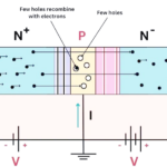
A bipolar junction transistor, or bjt, operates primarily through current control. You apply a small current to the bjt’s base terminal. This base current then dictates a much larger current flow between the collector and emitter terminals. Think of the bjt as a current amplifier. A tiny input current can control a significant output current. This makes the bjt very useful for amplifying signals. The output current is directly proportional to the input base current.
The magnitude of this base current significantly affects the bjt’s collector current across different operating regions:
-
Cut-off region: When you apply no base current (IB = 0), the bjt is off. No collector current flows (IC = 0).
-
Active region: Here, the collector current (IC) is directly proportional to the base current (IB). The relationship is IC = βIB. This means a small change in base current directly scales the collector current.
-
Saturation region: In this region, the collector current changes very little with further increases in base current. The collector current becomes more dependent on the voltage across the collector and emitter (VCE) rather than the base current. Increasing the base current further does not significantly increase the collector current.
Current Amplification and Beta Factor
The bjt’s ability to amplify current is a key feature. The “beta factor” (β), also known as the current gain, quantifies this amplification. It tells you how much collector current you get for every unit of base current. For example, a bjt with a beta of 100 means a 1mA base current will produce a 100mA collector current. This predictable current gain makes the bjt excellent for analog linearity. You can achieve very precise control over the output current. BJTs are also quite rugged in certain operating regions. They are suitable for applications needing a low parts count or where you need a predictable saturation voltage (VCE(sat)). This transistor type offers reliable performance in many circuits.
MOSFET Control: Voltage-Driven Operation
Gate Voltage as the Control Signal
A metal-oxide-semiconductor field-effect transistor, or mosfet, operates differently from a BJT. You control a mosfet using voltage, not current. You apply a voltage to the gate terminal. This gate voltage then creates an electric field. This field controls the current flow between the source and drain terminals. Think of the mosfet as a voltage-controlled switch or resistor. Its high input impedance means it draws very little current from the control signal. This makes the mosfet very energy efficient. You often find mosfets in high-power applications and designs needing faster switching speeds. They are excellent for energy-conscious designs because they generate less heat during operation.
Electric Field Effect and Channel Formation
The gate voltage is crucial for a mosfet’s operation. When you apply a voltage to the gate, it creates an electric field. This field attracts charge carriers to form a conductive path, or channel, between the source and drain. This channel allows current to flow. The gate-source voltage (VGS) directly influences the channel resistance in a mosfet. When VGS goes above the threshold voltage (VTH), a channel forms. This allows electrons to conduct.
In the linear (triode) mode, the mosfet acts like a variable resistor. The on-resistance in this mode is inversely proportional to the gate overdrive (VGS – VTH). This means increasing VGS above VTH reduces the channel resistance. The mosfet’s channel extends fully across the device in this mode. It behaves as a voltage-controlled resistor. The drain current is proportional to both the gate overdrive and the drain-source voltage (VDS). For small VDS, the on-resistance depends on VGS. This voltage control gives you precise command over the mosfet’s behavior. This transistor type offers superior performance in many modern electronic circuits.
Key Differences Between BJTs and MOSFETs
Understanding the core control mechanisms of BJTs and MOSFETs helps you see their distinct characteristics. These differences directly impact how you use each transistor in your designs. You will find that their input impedance, power efficiency, and switching speed vary significantly.
Input Impedance and Drive Requirements
The way you control a transistor directly affects its input impedance. A BJT, being current-controlled, requires a continuous base current to operate. This means a BJT has a relatively low input impedance. You must supply enough current to the base to turn it on and keep it in its desired operating region. This current draw can sometimes be a disadvantage in low-power applications or when you need to drive the transistor from a high-impedance source.
In contrast, a MOSFET is voltage-controlled. Its gate is isolated from the channel by an insulating layer. This gives the MOSFET an extremely high input impedance. You apply a voltage to the gate, and very little current flows into the gate terminal itself. This high input impedance is a major advantage. It means the MOSFET draws almost no current from the driving circuit. This makes MOSFETs ideal for situations where you want to minimize power consumption in the control signal. For example, the input impedance of a MOSFET amplifier often depends on the gate biasing resistor. This resistance can be in the megaohm range. You might see values like 1 MΩ or 2 MΩ. This high impedance simplifies the design of driver circuits.
Power Efficiency and Heat Generation
The control mechanism also influences power efficiency and heat generation. BJTs require a continuous base current, which consumes power. This power dissipation can lead to more heat generation, especially when the BJT is active. BJTs also experience charge storage effects. These effects can increase power losses during switching transitions.
MOSFETs, on the other hand, are generally more power-efficient, especially in switching applications. Because their gate draws very little current, they have lower static power dissipation. When a MOSFET is fully on, its resistance (Rds(on)) is very low, minimizing conduction losses.
Consider the quantitative differences in power dissipation during switching operations:
|
Feature |
MOSFETs |
BJTs |
|---|---|---|
|
Carrier Type |
Majority-carrier (unipolar) |
Minority-carrier (bipolar) |
|
Charge Storage |
No charge storage effects |
Charge storage occurs |
|
Switching Speed |
Nanosecond switching speeds |
Slow turn-off times (due to recombination) |
|
Switching Losses |
Lower switching losses |
Increased switching losses at high frequencies |
|
High-Frequency Suitability |
Ideal for high-frequency applications (SMPS, RF circuits) |
Less suitable for high-frequency applications |
This table shows that MOSFETs inherently have lower switching losses because they do not store charge in the same way BJTs do. This makes them a better choice for energy-conscious designs and high-frequency applications where minimizing heat is critical. You will find MOSFETs are often preferred for their superior power efficiency in many modern circuits.
Switching Speed and Capacitance Effects
The differences between BJT and MOSFET control also lead to significant variations in switching speed. MOSFETs generally offer faster switching speeds. This is because they are majority-carrier devices. Current flow involves only one type of charge carrier (electrons or holes). This means there are no minority carrier storage effects to slow down the turn-off process.
BJTs, however, are minority-carrier devices. They store charge in their base region when conducting. To turn a BJT off, you must remove this stored charge. This process takes time and limits the BJT’s switching speed, especially its turn-off time.
Both transistor types have parasitic capacitances that affect their high-frequency performance. For MOSFETs, these parasitic capacitances are crucial parameters. They significantly influence switching performance.
-
Ciss (input capacitance): This combines gate-source (Cgs) and gate-drain (Cgd) capacitances. It dictates how easily you can drive the input device and affects input losses. You must charge this capacitance for the MOSFET to operate.
-
Coss (output capacitance): This includes drain-source (Cds) and gate-drain (Cgs) capacitances. It impacts the output turn-off time. A large Coss can cause current to flow even when the gate is off, delaying complete turn-off.
-
Crss (gate-drain capacitance Cgd): Also known as feedback or reverse transfer capacitance, this capacitance significantly affects switching speed. A large Crss delays both the rise in drain current after turn-on and the fall in current after turn-off.
While BJTs can achieve very high transition frequencies (fT), especially specialized SiGe BJTs, MOSFETs often have higher maximum oscillation frequencies (fmax) due to their lower parasitic capacitances. This makes MOSFETs rule in digital and high-speed mixed-signal applications. BJTs, with their higher fT, still shine in RF circuits. Understanding these strengths and weaknesses helps you choose the right transistor for your specific needs.
|
Characteristic |
BJTs |
MOSFETs |
|---|---|---|
|
fT (Transition Frequency) |
Higher (100 GHz+ for SiGe BJTs) |
Lower |
|
fmax (Maximum Oscillation Frequency) |
Lower due to resistive losses |
Higher due to lower parasitic capacitances |
|
Application |
Shine in RF circuits |
Rule in digital & high-speed mixed-signal |
These key differences highlight why you might choose one transistor over the other. Your application’s specific requirements for input impedance, power efficiency, and switching speed will guide your decision.
Choosing Between BJTs and MOSFETs for Design
You must make a critical decision when designing electronic circuits: choosing between a BJT and a MOSFET. This choice depends heavily on your application’s specific needs. You will find that each transistor type offers unique strengths and weaknesses. Understanding these differences helps you select the best component for your project.
Analog vs. Switching Applications
A general rule of thumb guides many designers: use a MOSFET for switching applications and a BJT for small-signal analog applications. This rule highlights the core strengths of bjts and mosfets.
BJTs often provide superior performance in specific areas:
-
Signal Processing: You often choose BJTs for handling small, precise signals from sensors or in filters. They offer stability and consistent performance, especially when accuracy is critical.
-
High-Frequency Circuits: BJTs perform well up to a few hundred megahertz. This makes them suitable for radio amplifiers.
-
Power Circuits: You utilize BJTs, or their stronger versions like IGBTs, in heavy-duty systems. These include motor drives and industrial machines where they manage large currents and voltages.
-
Analog Circuits: You frequently use BJTs in circuits that process signals like sound. They provide good signal quality and gain. You find them in applications such as audio amplifiers and voltage regulators.
-
Switching Circuits: BJTs are effective for slower switching applications that require gain. Examples include motor controllers or simple relays.
BJTs offer high linearity and consistent gain, making them ideal for analog circuits. They respond well to small input currents, which is excellent for audio preamps and sensor inputs. You will find BJTs perform well in low-noise analog applications, such as radio frequency and instrumentation amplifiers. Their ease of biasing and stabilization simplifies design for linear mode operation. BJTs also show strong performance in amplifier stages, effective in push-pull and Class AB amplifier designs. You prefer them in discrete designs when simplicity and analog precision are key.
MOSFETs, on the other hand, excel in switching applications. Their ability to turn on and off quickly with minimal power loss makes them ideal for digital circuits, power supplies, and motor control. You can achieve fast, low-energy switching with a MOSFET.
Current and Voltage Handling Capabilities
The current and voltage handling capabilities of a transistor are vital considerations. BJTs have specific limitations you must understand. Power dissipation is a primary limit for BJTs. Common TO-3 packages can handle 150-300 watts at 25°C. However, practical designs use only a fraction of this capacity. Secondary breakdown in bipolar transistors further limits power dissipation at high voltages. Current gain and bandwidth decrease at high current in bipolar transistors. The Safe Operating Area (SOA) graph is crucial. It shows acceptable Vce and Ic limits. Factors like maximum bond wire current and secondary breakdown constrain these limits.
Here are typical current handling limits for common BJT packages:
|
BJT Package |
Typical Current Handling Limit |
|---|---|
|
TO-92 |
0.2A (e.g., 2N3904: 100mA-200mA) |
|
TO-220 |
Up to 30A (with appropriate heat sink) |
MOSFETs generally offer superior power handling capacity, especially in high-current, high-voltage switching applications. Their low on-resistance (Rds(on)) minimizes power loss when fully on. This makes them very efficient for managing significant power. You often choose MOSFETs for high-power applications due to their efficiency and ability to handle large currents without significant heat generation.
Design Complexity and Cost Factors
You also consider design complexity and cost when choosing between bjts and mosfets. Bipolar Junction Transistors (BJTs) generally lead to smaller factors in simple circuits. This can potentially reduce costs. However, MOSFETs can simplify circuit design in more complex systems. This is especially true for those involving sense gates or power operations.
Here is a comparison of design complexity:
|
Design Factor |
BJT Consideration |
MOSFET Consideration |
|---|---|---|
|
Circuit Complexity |
Simpler for linear applications |
Simpler for switching applications |
For simple analog circuits, a bjt might offer a more straightforward design. You can achieve good performance with fewer external components. For complex switching applications, a mosfet often simplifies the overall circuit design. Its high input impedance reduces the need for complex driver stages. This can lead to a more compact and efficient design. The initial cost of a single transistor might vary. However, the overall system cost depends on the complexity of the surrounding circuit. This includes driver components, heat sinks, and power supplies. You must weigh these factors to make an informed decision for your design.
You control a bjt with input current, making it a current amplifier. A mosfet responds to input voltage, acting as a voltage-controlled resistor. This fundamental difference shapes their input impedance, power efficiency, and switching characteristics. You observe these traits in every transistor application. For instance, a mosfet offers high input impedance and faster switching. A bjt provides predictable current amplification. Grasping these distinctions is crucial for informed circuit design. It guides your choice between bjts and mosfets for specific application needs.
FAQ
Why do MOSFETs switch faster than BJTs?
MOSFETs are majority-carrier devices. They do not store charge like BJTs. You do not need to remove stored charge to turn them off. This absence of charge storage allows for much quicker switching transitions.
When should I choose a BJT for my design?
You should choose a BJT for small-signal analog applications. They offer excellent linearity and predictable current gain. BJTs work well in audio amplifiers or sensor interfaces. They are also rugged in certain operating regions.
Can I replace a BJT with a MOSFET in any circuit?
No, you cannot always replace them directly. BJTs are current-controlled, and MOSFETs are voltage-controlled. You need to redesign the control circuit. Their different characteristics mean they suit different applications best.
See Also
IRF820 N-Channel MOSFET: Powering Management, Converters, and Motor Control
USB Controller Showdown: CYUSB3014-BZXI vs BZXC for Practical Applications
MCU Selection for Medical Equipment: STM32F401VCT6 Versus STR750FV2T6 Compared
Unlocking AD74413RBCPZ: Enhancing Industrial Process Control Capabilities
Bluetooth Robot Control: STM32F103C8T6 Microcontroller Implementation Guide