The NXP BAS321-QX Switching Diode SOD-323 FOR Power Management Circuits is a vital component. It features fast switching characteristics, including a 50 ns reverse recovery time. Its compact SOD323 package adds to its importance. This guide helps readers understand the Nxp Diode‘s key specifications. It also covers effective implementation, from datasheet interpretation to optimal PCB layout. Mastering this automotive-grade (AEC-Q101 qualified) component ensures robust and efficient circuit designs.
Key Takeaways
-
The BAS321-QX diode switches very fast. It has a 50 ns reverse recovery time. This makes it good for circuits that need quick changes.
-
This diode can handle high voltages. It works up to 200 V continuously. This makes it strong for power circuits.
-
The BAS321-QX is small. It comes in a SOD323 package. This saves space on circuit boards.
-
It is good for cars. The diode meets special car standards. It works well in tough car conditions.
-
Proper circuit board design is important. Short wires and good heat control help the diode work best.
NXP BAS321-QX Switching Diode: Core Specifications
This section explores the fundamental specifications of the NXP BAS321-QX. Designers must understand these details. They ensure proper circuit operation and reliability.
Electrical Characteristics
Electrical characteristics define how the diode behaves under normal operating conditions. The BAS321-QX handles a continuous reverse voltage of 200 V. It tolerates a repetitive peak reverse voltage of 250 V. These values show its robustness in power circuits. The maximum forward voltage is 1.25 V. This occurs at a specific forward current. The repetitive peak forward current reaches 625 mA. A low reverse leakage current is also important. This diode shows only 100 nA at 200 V when 200 V is applied in reverse. This low leakage minimizes power loss when the diode is off.
Maximum Ratings
Maximum ratings are critical limits. Exceeding them can damage the component. The BAS321-QX has a maximum forward surge current of 9 A. This rating is important for handling brief, high current spikes, such as during power-up. The total power dissipation is 300 mW. This value indicates how much power the diode can safely convert into heat without damage. Designers must consider these limits for reliable operation.
Thermal Characteristics
Thermal characteristics describe the diode’s performance with temperature. The operating temperature range is wide. It goes up to 150 °C. This high limit makes the BAS321-QX suitable for demanding environments. It is especially useful in automotive applications, where temperatures can vary greatly. Proper thermal management is always important to maintain performance and lifespan.
Diode Capacitance
Diode capacitance affects switching speed. The BAS321-QX features a very low maximum diode capacitance of 2 pF. This low capacitance is key for fast switching applications. It allows the diode to turn on and off quickly. This characteristic directly contributes to its 50 ns reverse recovery time. The NXP BAS321-QX Switching Diode SOD-323 FOR Power Management Circuits excels in high-frequency designs due to this feature. This low capacitance helps maintain signal integrity in high-speed circuits.
Datasheet Interpretation: Key Parameters
This section guides readers on interpreting the datasheet graphs and tables for the BAS321-QX. It focuses on the practical implications of each key parameter. These parameters affect circuit performance and reliability.
Forward Curve Analysis
The forward curve illustrates the relationship between forward voltage (Vf) and forward current (If). Designers use this curve to predict the voltage drop across the diode at a given current. This voltage drop directly impacts power loss and heat generation within the circuit. A lower forward voltage at the operating current means less power dissipation. This improves overall circuit efficiency. Engineers select the appropriate operating point from this curve.
Reverse Recovery Time
Reverse recovery time (trr) is a critical parameter for switching diodes. The BAS321-QX boasts a fast 50 ns reverse recovery time. This value indicates how quickly the diode transitions from a conducting state to a non-conducting state. A shorter reverse recovery time minimizes energy losses during switching. This characteristic is vital for high-frequency applications. It allows the diode to switch rapidly without significant power dissipation. Fast switching speed improves the efficiency of power converters and other high-frequency circuits.
Reverse Leakage Current
Reverse leakage current (Ir) flows when the diode is reverse-biased, meaning it is supposed to be off. The BAS321-QX exhibits a very low reverse leakage current of 100 nA at 200 V. A low leakage current is beneficial for several reasons. It reduces power consumption when the diode is not conducting. This is especially important in battery-powered devices or circuits with low-power standby modes. Low leakage also contributes to overall system efficiency and reliability.
Breakdown Voltage
Breakdown voltage (Vr) represents the maximum reverse voltage a diode can withstand before it starts conducting in the reverse direction. The BAS321-QX has a continuous reverse voltage of 200 V and a repetitive peak reverse voltage of 250 V. Designers must ensure the circuit’s maximum expected reverse voltage does not exceed these ratings. Exceeding the breakdown voltage can permanently damage the diode. Proper selection of breakdown voltage ensures the diode protects the circuit from voltage spikes and transient events.
BAS321-QX in Power Management Circuits
The BAS321-QX diode plays a crucial role in many power management circuits. Its unique combination of speed, voltage rating, and compact size makes it highly versatile. Designers classify it as a general-purpose, power, and switching diode. This section explores its common uses and how to operate it effectively.
Common Applications
The BAS321-QX finds use in various power management applications. Its fast switching speed makes it ideal for high-frequency circuits.
-
Switch-Mode Power Supplies (SMPS): Designers often use it in SMPS for rectification and clamping. Its quick response helps maintain efficiency.
-
DC-DC Converters: It serves as a freewheeling diode or a blocking diode in these converters. It handles voltage spikes and ensures smooth operation.
-
Automotive Systems: The diode’s AEC-Q101 qualification means it withstands harsh automotive environments. It protects sensitive components from voltage transients.
-
Reverse Polarity Protection: Its robust reverse voltage ratings make it suitable for protecting circuits from incorrect power connections.
-
Signal Rectification: In high-frequency signal processing, it rectifies signals with minimal distortion due to its low capacitance.
The NXP BAS321-QX Switching Diode SOD-323 FOR Power Management Circuits offers a reliable solution for these diverse needs.
Optimal Operating Point
Selecting the optimal operating point for the BAS321-QX ensures both efficiency and longevity. Designers must consider several factors:
-
Forward Current (If): Operate the diode below its repetitive peak forward current (625 mA). Refer to the forward curve to determine the voltage drop at the chosen current. This helps calculate power dissipation.
-
Reverse Voltage (Vr): Ensure the maximum reverse voltage in the circuit stays well below the continuous reverse voltage (200 V) and repetitive peak reverse voltage (250 V). This prevents breakdown and damage.
-
Power Dissipation (Pd): Calculate the power dissipated by the diode (Vf * If + Vr * Ir). Keep this value below the maximum power dissipation (300 mW). Proper thermal management becomes essential, especially at higher temperatures.
-
Temperature: The diode operates up to 150 °C. However, lower operating temperatures generally extend component life and improve reliability.
Tip: Always include a safety margin when designing. Do not operate the diode consistently at its absolute maximum ratings.
Series and Parallel Use
Designers can use the BAS321-QX in series or parallel configurations for specific requirements.
-
Series Connection: Connecting diodes in series increases the total reverse voltage capability. For example, two BAS321-QX diodes in series can withstand a higher reverse voltage than a single diode. However, designers must ensure proper voltage sharing across each diode. Mismatched reverse leakage currents can cause uneven voltage distribution.
-
Parallel Connection: Connecting diodes in parallel increases the total forward current capability. This allows the circuit to handle higher currents than a single diode. However, current sharing becomes a critical concern. Differences in forward voltage drop (Vf) among parallel diodes can lead to one diode carrying more current than others. This can cause thermal runaway.
-
Best Practice: Use diodes with closely matched characteristics for parallel operation. Consider adding small series resistors to help balance current flow.
-
These configurations require careful design and component selection to ensure reliable performance.
BAS321-QX PCB Layout Best Practices

Effective PCB layout is crucial for maximizing the performance and reliability of the BAS321-QX. This section offers practical advice for designing the PCB layout specifically for this diode. Designers must consider its very small SOD323 (SC-76) plastic package.
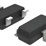
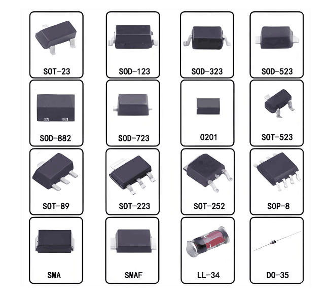
SOD-323 Package and Footprint
The SOD-323 package is a tiny, surface-mount device. Its small size demands precise footprint design on the PCB.
-
Accurate Dimensions: Designers must use the exact dimensions specified in the datasheet for the land pattern. Incorrect pad sizes can lead to poor solder joints or tombstoning during reflow soldering.
-
IPC Standards: Adhering to IPC-7351 standards for surface mount device footprints is a best practice. These standards provide guidelines for pad geometry, solder mask openings, and silkscreen markings.
-
Pad Size: Ensure the copper pads are large enough for reliable soldering but not so large that they cause solder bridging. The datasheet typically provides recommended pad dimensions.
-
Solder Mask: The solder mask opening should be slightly larger than the copper pad. This creates a “solder dam” that helps prevent solder from flowing away from the pad.
Tip: Always verify the footprint against the manufacturer’s recommendations and consider your assembly house’s capabilities.
Trace Routing for Switching
The BAS321-QX is a fast switching diode. Proper trace routing is essential to leverage its speed and prevent performance degradation.
-
Short and Direct Traces: Keep traces connected to the diode as short and direct as possible. This minimizes parasitic inductance and resistance, which can slow down switching and increase voltage spikes.
-
Minimize Loop Areas: High-frequency switching currents create magnetic fields. Large current loops induce noise and electromagnetic interference (EMI). Designers should route traces to minimize the area enclosed by the current path (e.g., from the power source, through the diode, and back to ground).
-
Ground Plane: Implement a solid ground plane beneath the diode and its associated components. A continuous ground plane provides a low-impedance return path for switching currents. It also helps dissipate heat and reduces noise.
-
Trace Width: Ensure traces carrying significant current have adequate width. This prevents excessive voltage drop and localized heating. Refer to current density guidelines for PCB traces.
Thermal Management
Despite its small size, the BAS321-QX dissipates power, especially at higher currents or temperatures. Effective thermal management is crucial for its long-term reliability.
-
Copper Pours: Connect the diode’s pads to large copper pours or planes. Copper acts as a heat sink, drawing heat away from the component.
-
Larger Pads: Design the pads slightly larger than strictly necessary for soldering, if space allows. This increases the thermal contact area with the PCB.
-
Thermal Vias: For more demanding thermal conditions, designers can place thermal vias under the pads. These vias connect the top layer pads to internal ground or power planes, further enhancing heat transfer away from the diode.
-
Heat Dissipation: The small SOD323 package has limited surface area for convection cooling. Relying on the PCB copper for heat spreading is often the primary thermal management strategy.
Component Proximity
The placement of the BAS321-QX relative to other components significantly impacts circuit performance.
-
Close to Switching Elements: Place the diode as close as possible to the switching IC or inductor it works with. This minimizes the length of high-frequency current paths.
-
Close to Capacitors: In rectifier or clamping applications, position the diode near the filter capacitors. This reduces parasitic inductance in the filtering loop, improving ripple reduction and transient response.
-
Avoid Sensitive Signals: Keep the diode and its associated high-current switching traces away from sensitive analog signals or control lines. This prevents noise coupling and ensures signal integrity.
-
Power Loops: Optimize the layout to create compact power loops. For instance, in a buck converter, the loop formed by the input capacitor, switching FET, diode, and output capacitor should be as small as possible. This compact layout is especially important for the NXP BAS321-QX Switching Diode SOD-323 FOR Power Management Circuits due to its fast switching speed.
The NXP BAS321-QX Switching Diode SOD-323 FOR Power Management Circuits plays a critical role in modern power management. Its fast switching, low capacitance, and robust voltage ratings are essential for successful designs. Effective PCB layout, guided by datasheet insights and best practices for the SOD323 package, maximizes performance and reliability. Designers should apply these principles to achieve robust and efficient circuit operation with this automotive-grade component. Meticulous component selection and layout are invaluable in electronics design.
What is the primary advantage of the BAS321-QX diode?
The BAS321-QX offers a fast 50 ns reverse recovery time. This allows it to switch quickly. Its low 2 pF diode capacitance also contributes to its speed. These features make it ideal for high-frequency power circuits.
Is the BAS321-QX suitable for automotive applications?
Yes, the BAS321-QX is AEC-Q101 qualified. This means it meets the strict reliability standards for automotive components. It performs well in demanding vehicle environments.
How does the small SOD323 package impact PCB layout?
The tiny SOD323 package requires precise PCB footprint design. Designers must use short, direct traces. They also need effective thermal management. This ensures the diode performs optimally and reliably.
What is the maximum reverse voltage the BAS321-QX can withstand?
The BAS321-QX can withstand a continuous reverse voltage of 200 V. It also handles a repetitive peak reverse voltage of 250 V. These ratings provide robustness in power circuits.
Can the BAS321-QX be used in parallel for higher current?
Designers can use the BAS321-QX in parallel. This increases the total forward current capability. However, they must ensure careful current sharing. Mismatched diodes can lead to uneven current distribution.
See Also
Unlock Peak Performance: LPQ252-CEF for Superior Power Management
NXP Microcontrollers: Driving Automotive Electronics with Core Chip Power
USB Controller Showdown: CYUSB3014-BZXI vs. BZXC Selection and Use
Coilcraft XPL2010: High-Performance Inductors for Optimal VRM/VRD Design