Understanding YAGEO’s MLCC datasheets allows engineers to make informed choices when selecting components. These datasheets provide critical information about capacitor performance, reliability, and compatibility with various applications. Designers can optimize circuits by analyzing specifications like capacitance, voltage ratings, and temperature stability.
Mastering datasheets for MLCC ceramic capacitors ensures precision in electronic designs and helps achieve long-term reliability. Engineers who interpret this data effectively can enhance device functionality while minimizing risks.
Key Takeaways
-
Learning YAGEO’s MLCC datasheets helps pick the right parts. Check details like capacitance, voltage limits, and temperature stability for better designs.
-
YAGEO’s MLCC capacitors work well and are dependable. They are great for gadgets, cars, and green energy projects. Pick the type that fits your needs.
-
Look at important details like capacitance tolerance and voltage limits. Always leave extra room in your design to avoid capacitor problems.
-
Think about how temperature and DC-BIAS change capacitance. Use datasheet graphs to see how they perform in real life.
-
Handle soldering and storage carefully to make YAGEO’s MLCC capacitors last longer. Good care stops damage and improves how they work.
Overview of YAGEO’s MLCC Capacitors
YAGEO’s MLCC capacitors represent a versatile solution for modern electronic devices. These capacitors offer reliability, stability, and environmental compliance, making them suitable for diverse applications. With a broad portfolio that includes general-purpose, high-voltage, and ultra-small size capacitors, YAGEO addresses the needs of industries ranging from consumer electronics to automotive systems.
Applications of YAGEO’s MLCC Capacitors
YAGEO’s MLCC capacitors serve critical roles in various applications:
-
Consumer Electronics: Smartphones, laptops, and smart home devices rely on MLCCs for power management and signal integrity.
-
Automotive Systems: Capacitors enhance infotainment systems, safety devices, and electric vehicle components.
-
Renewable Energy: Solar inverters use Class 1 capacito
-
rs to improve efficiency in MPPT circuits.
-
Telecommunications: 5G base stations benefit from capacitors that maintain signal integrity and reduce insertion losses.
-
Industrial Automation: Servo motor controls, PLC controllers, and automation equipment depend on MLCCs for precision and reliability.
Features of the CC NPO Series
The CC NPO series stands out for its exceptional characteristics:
-
Class I Dielectric: Ensures superior stability and eliminates capacitance aging.
-
Wide Temperature Range: Operates effectively up to 125°C, making it suitable for demanding environments.
-
Environmental Compliance: RoHS and halogen-free certifications align with sustainability standards.
-
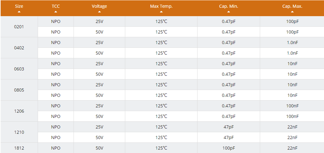
Size and Capacitance Options: Available in sizes like 0201 and 0805, with capacitance values ranging from 0.47pF to 100nF.
Benefits of Using YAGEO’s MLCC Capacitors
YAGEO’s MLCC capacitors offer several advantages:
-
Reliability: IEC60068 qualification ensures dependable performance.
-
Versatility: A diverse product range meets the requirements of various electronic devices.
-
Enhanced Performance: High Q capacitors improve signal quality in communication systems.
-
Market Growth Alignment: The global MLCC market, projected to grow to USD 11.9 billion by 2032, highlights the increasing demand for these components.
YAGEO’s commitment to innovation and environmental protection makes its MLCC capacitors a preferred choice for engineers seeking high-quality solutions.
Key Specifications in a Capacitor Datasheet
Understanding the key specifications in a capacitor datasheet is essential for selecting the right component for any application. These specifications provide detailed insights into the performance, reliability, and limitations of capacitors under various conditions. Below are three critical parameters to consider when analyzing a capacitor datasheet.
Capacitance and Tolerance
Capacitance is the primary function of a capacitor, representing its ability to store electrical charge. It is measured in farads (F), with most MLCCs offering values in microfarads (µF), nanofarads (nF), or picofarads (pF). The rated capacitance is the nominal value specified by the manufacturer, but real-world conditions often cause slight variations. Tolerance indicates the acceptable range of deviation from the rated capacitance. For example, a capacitor with a rated capacitance of 10 nF and a tolerance of ±5% may have an actual capacitance between 9.5 nF and 10.5 nF.
Temperature and frequency can also affect capacitance. Performance graphs in datasheets often illustrate how capacitance varies with these factors, helping engineers predict behavior in specific environments. For instance, YAGEO’s MLCC capacitors, including the CC NPO series, exhibit minimal capacitance variation due to their Class I dielectric, ensuring high stability.
Tip: Always consider the tolerance and environmental factors when selecting a capacitor to ensure it meets the application’s requirements.
Voltage Ratings and Safety Margins
Voltage ratings define the maximum voltage a capacitor can handle without breaking down. The rated voltage, often listed as the DC voltage, is the upper limit under standard operating conditions. Exceeding this value can lead to dielectric failure or permanent damage. For safety, engineers should design circuits with an operating voltage well below the rated voltage, typically by applying a safety margin of 20-30%.
Datasheets also specify other voltage-related parameters, such as surge voltage and transient voltage. Surge voltage represents the maximum voltage the capacitor can withstand for a short duration, while transient voltage accounts for brief spikes during operation. For example, YAGEO’s MLCC capacitors are designed to handle these variations, ensuring reliability in demanding applications like automotive systems and telecommunications.
|
Voltage Parameter |
Description |
|---|---|
|
Rated Voltage |
Maximum continuous voltage the capacitor can handle. |
|
Surge Voltage |
Maximum voltage for short durations. |
|
Operating Voltage |
Recommended voltage for safe and reliable operation. |
|
Transient Voltage |
Short-term voltage spikes during operation. |
Note: Always verify the operating voltage of your circuit and ensure it remains within the capacitor’s rated voltage limits.
ESR and Impedance
Equivalent Series Resistance (ESR) is a critical parameter that represents the resistive component of a capacitor. It affects the efficiency and heat generation of the capacitor during operation. Lower ESR values indicate better performance, especially in high-frequency applications. Impedance, on the other hand, is the total opposition a capacitor offers to alternating current (AC). It combines both the resistive (ESR) and reactive components.
The relationship between impedance (Z), angular frequency (ω), and capacitance (C) is given by the formula:
Z = 1 / (jωC)
At the self-resonant frequency, the impedance equals the ESR, and the capacitor exhibits its minimum impedance. For example, a 10 nF capacitor may have a minimum impedance of 60 mΩ at 200 MHz, as shown in datasheets. This information helps engineers select capacitors with optimal ESR and impedance values for their designs.
|
Parameter |
Value |
|---|---|
|
ESR |
60 mΩ |
|
Frequency |
200 MHz |
Tip: When analyzing ESR and impedance, consider the operating frequency of your circuit to ensure compatibility with the capacitor’s performance characteristics.
Dissipation Factor and Losses
The dissipation factor (Df) is a critical parameter in a capacitor datasheet. It measures the energy lost as heat during the capacitor’s operation. This factor directly impacts the efficiency of the capacitor, especially in high-frequency applications. A lower dissipation factor indicates better performance, as less energy is wasted. Engineers often prioritize capacitors with minimal Df values for circuits requiring high precision and reliability.
Datasheets typically specify the dissipation factor at a particular frequency and temperature. For example, YAGEO’s MLCC capacitors, including the CC NPO series, exhibit low Df values due to their Class I dielectric material. This characteristic ensures minimal energy loss, making them ideal for applications like telecommunications and industrial automation.
However, discrepancies in Df measurements across manufacturers can complicate component selection. Studies have shown that published Df values often differ significantly from reference measurements. For instance:
-
Published Df values are generally lower than reference measurements, especially at higher frequencies like 1 GHz.
-
Variability in measurement methods across manufacturers contributes to these discrepancies.
-
Material characterization inconsistencies, such as dielectric constant (Dk) variations of ±10%, further affect accuracy.
These findings highlight the importance of verifying datasheet specifications through independent testing. Engineers should consider these factors when selecting capacitors to ensure optimal performance and cost control.
Tip: Always cross-reference the dissipation factor with the operating frequency of your circuit. This practice helps avoid unexpected losses and ensures signal integrity.
Temperature Characteristics and Stability
Temperature significantly affects a capacitor’s performance. The temperature coefficient, often listed in the capacitor datasheet, indicates how capacitance changes with temperature. YAGEO’s MLCC capacitors, particularly the CC NPO series, excel in this area due to their Class I dielectric. These capacitors maintain stable capacitance across a wide temperature range, ensuring reliable operation in demanding environments.
For instance, the CC NPO series operates effectively up to 125°C without significant changes in capacitance. This stability makes them suitable for applications like automotive systems and renewable energy, where temperature fluctuations are common. Engineers can rely on these capacitors to deliver consistent performance, even under extreme conditions.
Datasheets often include graphs showing capacitance versus temperature. These graphs help engineers predict how a capacitor will behave in specific environments. For example, a capacitor with a temperature coefficient of ±30 ppm/°C will exhibit minimal capacitance variation, ensuring precision in sensitive circuits.
Note: When designing circuits, always account for the operating temperature range. This consideration ensures the capacitor performs as expected under real-world conditions.
Interpreting Performance Metrics in Capacitor Datasheets
Capacitance vs. Temperature Graphs
Capacitance vs. temperature graphs provide critical insights into how a capacitor’s performance characteristics change with temperature variations. These graphs, often included in a capacitor data sheet, illustrate the stability of capacitance across a specified temperature range. For example, capacitors with Class I dielectrics, such as YAGEO’s CC NPO series, exhibit minimal capacitance variation, ensuring reliable operation in temperature-sensitive applications.
The temperature coefficient, expressed in parts per million per degree Celsius (ppm/°C), quantifies this variation. A lower coefficient indicates better stability. For instance, a capacitor with a coefficient of ±30 ppm/°C will maintain consistent capacitance even when exposed to extreme temperatures. Engineers rely on these graphs to select capacitors that meet the thermal demands of their designs, such as automotive systems or industrial automation equipment.
Tip: Always review the capacitance vs. temperature graph to ensure the capacitor performs reliably within the operating temperature range of your application.
DC-BIAS Effects on Capacitance
DC-BIAS refers to the direct current voltage applied to a capacitor during operation. This voltage can significantly impact the capacitance value, especially in Class II and III dielectrics. As the DC-BIAS increases, the capacitance often decreases due to the polarization of the dielectric material. Understanding this relationship is crucial for designing circuits that require precise capacitance values under varying voltage conditions.
For example, a capacitor rated at 10 nF may exhibit a capacitance drop of up to 40% when subjected to a DC-BIAS of 10V. Engineers must account for this effect when selecting capacitors for high-voltage applications, such as power supplies or telecommunications equipment.
The following table highlights how performance characteristics, such as dissipation factor (Df) and quality factor (Q), vary with voltage:
|
Metric |
Voltage (1V) |
Voltage (10V) |
|---|---|---|
|
Dissipation Factor (Df) |
0.014 – 0.025 |
0.025 – 0.046 |
|
Quality Factor (Q) |
40.27 – 72.21 |
19.65 – 40.95 |
This data underscores the importance of evaluating a capacitor’s behavior under real-world operating conditions.
Note: When designing circuits, always consider the DC-BIAS effect to ensure the capacitor maintains its intended performance characteristics.
Frequency Response and Impedance Curves
Frequency response and impedance curves reveal how a capacitor behaves across different frequencies. These curves help engineers understand the capacitor’s impedance, which combines resistance (ESR) and reactance, at various frequencies. Impedance decreases with increasing frequency until it reaches the self-resonant frequency, where it equals the ESR. Beyond this point, the capacitor behaves inductively, and impedance increases.
Key methods for measuring frequency response include:
-
Using an op-amp with a specified slew rate to evaluate capacitor performance in high-frequency applications.
-
Verifying performance metrics through practical measurements, such as total harmonic distortion (THD) and output signal characteristics.
These techniques ensure the capacitor meets the required performance characteristics for applications like telecommunications and renewable energy systems. For instance, a capacitor with a minimum impedance of 60 mΩ at 200 MHz would perform well in high-frequency circuits.
Tip: Analyze the frequency response and impedance curves to select capacitors that align with the operating frequency of your circuit.
Practical Considerations for YAGEO’s MLCC Capacitors
Mechanical Stress and Mounting Guidelines
Mechanical stress can significantly impact the performance and reliability of a capacitor. Engineers must consider stress factors during the mounting process to prevent damage. For YAGEO’s MLCC capacitors, stress analysis data highlights the importance of proper handling and mounting techniques.
|
Test Type |
Findings |
|---|---|
|
Flex Stress (Sharp Pin) |
80-90% failure rate after 2000 hours |
|
Flex Stress (Blunt Pin) |
24% failure rate after 2000 hours |
|
Thermal Vacuum Test |
Lower stress level compared to dry heat; DCL failures after reflow mounting |
|
Thermo-mechanical Stress |
No microcracks observed; all parts passed specifications |
|
Dry Heat Test |
Higher degradation rate at 125°C; initial failures noted after 500 hours |
To minimize mechanical stress, engineers should follow these guidelines:
-
Use flexible PCB designs to reduce stress transfer to the capacitor.
-
Avoid excessive force during soldering or reflow processes.
-
Ensure proper alignment of components to prevent uneven stress distribution.
Soldering and Cooling Best Practices
Soldering plays a critical role in ensuring the durability of MLCC capacitors. Improper soldering techniques can lead to thermal cracks or electrical failures. YAGEO recommends adhering to industry-standard soldering profiles to maintain the integrity of the capacitor.
Key soldering tips include:
-
Use a preheating stage to reduce thermal shock.
-
Maintain a controlled soldering temperature to avoid overheating.
-
Allow gradual cooling to prevent thermal stress.
Cooling is equally important. Rapid cooling can induce cracks due to thermal contraction. Engineers should implement controlled cooling methods to ensure the capacitor retains its structural and electrical characteristics.
Storage Conditions for Longevity
Proper storage conditions are essential for preserving the performance of YAGEO’s MLCC capacitors. Exposure to high humidity or extreme temperatures can degrade the dielectric material and reduce the capacitor’s lifespan.
|
Stress Type |
Description |
|---|---|
|
CTE Mismatch |
Simulated extreme conditions; no internal damage found |
|
Mechanical Overstress |
Induced cracks; monitored electrical behavior changes |
|
Thermal Vacuum |
Lower stress levels; observed failures in specific groups |
|
Dry Heat |
Higher temperatures led to increased failure rates; key parameter for initiating failures |
To ensure longevity:
-
Store capacitors in a dry, temperature-controlled environment.
-
Use vacuum-sealed packaging to prevent moisture absorption.
-
Rotate inventory to avoid prolonged storage periods.
By following these practices, engineers can maximize the reliability and lifespan of YAGEO’s MLCC capacitors in their applications.
Advanced Insights Beyond the Capacitor Datasheet
DC-BIAS Measurement Techniques
DC-BIAS measurement techniques provide deeper insights into capacitor performance under real-world conditions. These methods analyze how capacitance changes when direct current voltage is applied, revealing critical characteristics that standard datasheets may not fully capture. Engineers use advanced procedures to ensure accurate measurements, especially for capacitors in high-voltage applications.
Low current measurement practices optimize accuracy during very low-frequency capacitance-voltage (C-V) tests. Shielding the device and using triax cables reduce noise interference, ensuring precise readings. Setting expected capacitance (expected_C) to zero and expected resistance (expected_R) to 1E12 minimizes errors during initial tests. Adjusting these values further refines results for specific applications.
Quasistatic C-V measurements involve applying a small AC voltage signal and measuring the resulting current. This technique derives capacitance by sampling material at different depths within the device. Engineers also perform DC resistance measurements through I-V tests to validate compatibility with very low-frequency approaches.
The table below summarizes key procedures:
|
Procedure/Technique |
Description |
|---|---|
|
Low Current Measurement Practices |
Optimize accuracy using shielding and triax cables. |
|
Expected Values for C and R |
Set expected_C to 0 and expected_R to 1E12 to avoid errors. |
|
DC Resistance Measurement |
Perform I-V tests to confirm compatibility with VLF C-V methods. |
|
Quasistatic C-V Measurement |
Apply small AC voltage signals to derive capacitance. |
|
Capacitance Measurement |
Use simultaneous AC and DC sources to sample material at different depths. |
These techniques enhance understanding of capacitor behavior, ensuring reliable performance in demanding applications like telecommunications and power systems.
Beyond-the-Datasheet Models and Their Applications
Datasheets provide essential information, but advanced models extend this understanding by simulating real-world conditions. These models analyze parameters like ESR, insulation resistance, and dielectric behavior under varying test conditions. Engineers use these insights to predict performance and optimize designs.
Equivalent Series Resistance (ESR) measurements reveal heat generation and performance degradation. Insulation resistance depends on chip design and test conditions, influencing evaluations of chip capacitors. Dielectric behavior varies significantly between Class I and Class II dielectrics, with Class II showing greater dependence on test conditions.
The table below highlights these parameters:
|
Parameter |
Description |
|---|---|
|
ESR |
Indicates performance degradation due to heat generation. |
|
Insulation Resistance |
Strongly related to chip design and test conditions. |
|
Dielectric Behavior |
Class II dielectrics show significant dependence on test conditions. |
Beyond-the-datasheet models help engineers select capacitors with optimal characteristics for specific applications. For example, these models guide the design of circuits requiring high stability, such as industrial automation systems. By leveraging these advanced insights, engineers can ensure capacitors meet stringent performance requirements.
Mastering YAGEO’s MLCC capacitor datasheets equips engineers with the knowledge to select components that align with their design goals. These datasheets provide critical insights into performance metrics, ensuring optimal functionality and reliability in electronic systems.
Tip: Engineers should regularly consult datasheets to stay informed about key specifications and advanced techniques.
Applying these insights allows designers to create robust circuits that meet industry standards. By understanding the nuances of YAGEO’s MLCC capacitors, professionals can enhance the efficiency and longevity of their electronic designs.
Unlock the full potential of your projects by leveraging the power of informed component selection!
### What does “Class I Dielectric” mean in YAGEO’s MLCC capacitors?
Class I dielectric refers to capacitors with high stability and precision. These capacitors exhibit minimal capacitance variation across temperature and voltage changes. YAGEO’s CC NPO series uses Class I dielectric, ensuring zero capacitance aging and reliable performance in precision applications.
How do I interpret the capacitance tolerance in a datasheet?
Capacitance tolerance indicates the acceptable range of deviation from the rated capacitance. For example, a 10 nF capacitor with ±5% tolerance may vary between 9.5 nF and 10.5 nF. This helps engineers ensure compatibility with circuit requirements.
Why is ESR important for capacitor selection?
Equivalent Series Resistance (ESR) affects heat generation and efficiency. Lower ESR values improve performance, especially in high-frequency circuits. YAGEO’s MLCC capacitors provide low ESR, making them ideal for applications like telecommunications and power supplies.
What storage conditions ensure the longevity of MLCC capacitors?
Store capacitors in a dry, temperature-controlled environment. Vacuum-sealed packaging prevents moisture absorption. Avoid prolonged storage periods by rotating inventory. These practices preserve the dielectric material and extend the capacitor’s lifespan.
How does DC-BIAS affect capacitance?
DC-BIAS reduces capacitance in Class II and III dielectrics due to dielectric polarization. For instance, a 10 nF capacitor may lose up to 40% capacitance under a 10V DC-BIAS. Engineers must account for this effect in high-voltage applications.
Tip: Always review DC-BIAS graphs in datasheets to predict real-world performance.
See Also
Understanding MC9S12DJ256MFUE Specs for Automotive Use
Three Key Features of SPC5605BMLL6 and SPC5607BMLL6 ECUs
Complete Overview of AD1940YSTZ and AD1941YST Automotive DSPs
Three Notable Features of R5F64219JFB in Audio Devices
Reasons to Select Coilcraft XPL2010 for VRM and VRD